3D Optical Profilometers
A Method for Instantaneous and Accurate Measurement of Undercuts
Mechanical parts require high strength as well as precise dimensions and accuracy so that machinery and equipment can perform as intended. With that said, these strict requirements greatly affect the cost of the equipment and machinery as they consist of a collection of mechanical parts. Since priority is given to the performance of machinery and equipment, cost reductions for mechanical parts are often not adequately considered during the design stage.
The principle behind undercutting is to reduce costs while facilitating machining by easing the tolerance settings on mechanical parts. This page explains what undercuts are and how to measure them after machining. In addition, it presents a solution to the problems inherent in conventional measurement methods.
Undercuts
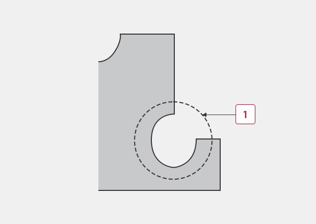
An undercut is a recess that is milled in a corner when the cutting blade cannot create a sharp edge. Milling undercuts reduces machining costs and time.
There is another type of machining similar to undercutting called clearance. Undercuts are made in small areas such as sharp edges, while clearance is made over a wider area. In other words, undercuts are included in clearance and are sometimes referred to as clearance.
-
1Undercut
Types of Undercuts
Undercuts and clearances are design techniques that can efficiently be used in a number of circumstances:
- When machining locations do not require fitting tolerances
- When reducing burrs during internal tooth machining
- When reducing the number of processes where sharp edges are machined
Undercuts at Locations Not Requiring Fitting Tolerance
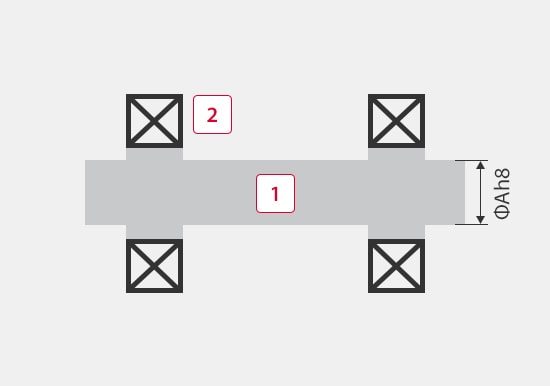
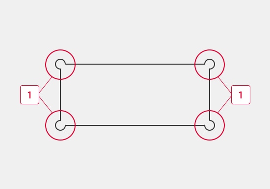
Strict tolerances increase the cost of machining mechanical parts. For example, the figures below show the insertion of a shaft into bearings. In the “Before” figure, a strict tolerance is applied to the entire shaft. This kind of design makes both shaft machining and bearing insertion difficult, increasing costs.
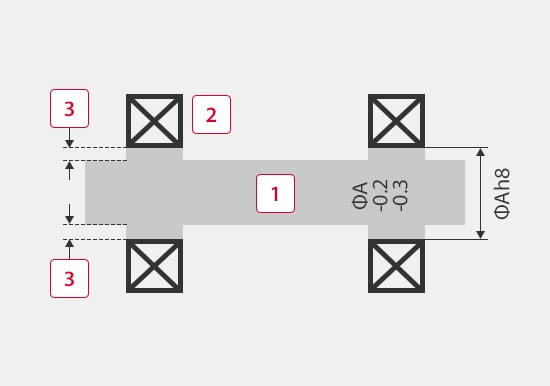
In such cases, as shown in the “After” drawing, a strict tolerance should be applied only to the engaging sections on the shaft and bearings, and undercuts should be added to give a larger tolerance to other sections. This design makes machining and assembly easy, reducing the total costs.
Before
-
1Shaft
-
2Bearing
After
-
1Shaft
-
2Bearing
-
3Undercut
Undercuts That Reduce Time Required for Pocket Machining
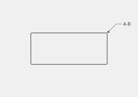
Undercuts may be specified in designs where the tool shape was taken into consideration. When a pocket is milled as shown below, with the instruction in the “Before” figure, the round shape of the blade unavoidably remains in the corners. To prevent this, it is necessary to use an even smaller tool to reduce the round shape in the corners. However, machining with a smaller-diameter tool requires time, increasing the cost. For example, If a pocket needs to be milled to have right-angled corners at an engaging section, additional machining is required after milling, further increasing the cost.
In these cases, milling undercuts as shown in the “After” figure can reduce the time required for machining. By adding undercuts in the corners, the round shape of the tool which remains in the corners can be ignored, allowing a tool with a diameter suitable for the machining to be used. This reduces the machining time and eliminates the need for additional machining, even in the engaging sections of products which have right-angle corners, achieving a significant cost reduction.
Before
After
-
1Undercut
Actual Undercut Measurement
As stated earlier, adding undercuts can reduce costs. Undercuts of course need to have sizes and shapes that fall within the tolerances specified in design drawings. This is especially true for undercuts on precision parts that have tolerances within 0.5 mm (0.02″) or less. Undercuts are milled in recessed locations and have complex shapes which means they can only be used to reduce costs when they have been verified as having the proper design sizes and shapes.
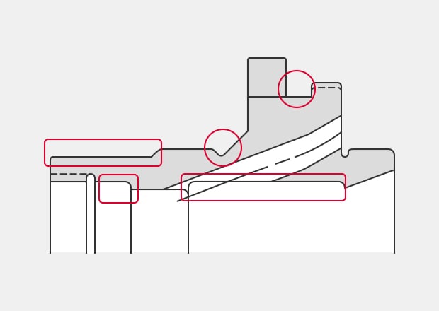
The figure on the right shows an example of a drawing specifying undercuts or clearance. As shown in the figure, many undercuts are specified in actual drawings. Machined products need to be measured to confirm that all undercuts fall within the specified tolerances.
Problems in Conventional Undercut Measurement
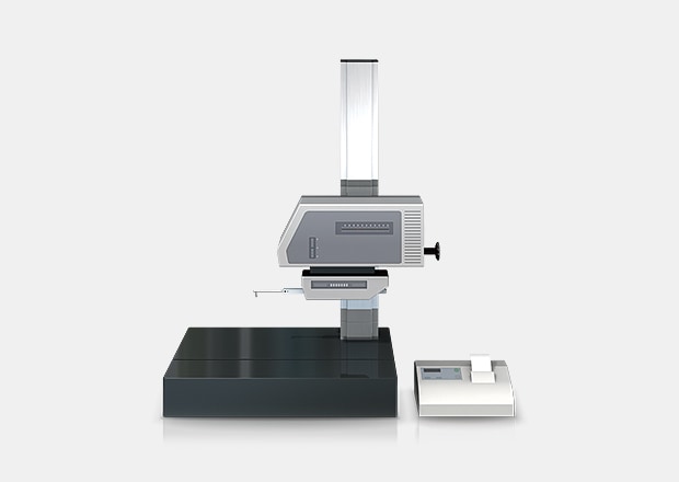
Conventional tools used to measure undercuts are profile measurement systems.
A profile measurement system measures and records the profile of a target by tracing its surface with a stylus.
In recent years, profile measurement systems that have been use a laser instead of a stylus to measure complex shapes by tracing the profile in a non-contact manner. Some models are even able to perform measurement of both the top and bottom surfaces.
Problems in Undercut Measurement Using a Profile Measurement System
Undercut measurement using a profile measurement system involves the following problems.
- Measurement work requires much time, including time for fastening the target to a jig and leveling it. Additionally, knowledge and skills related to using a profile measurement system are required in order to level a target accurately.
- When measuring undercuts at recessed locations, it is difficult to trace the desired measurement position with a stylus. Even slight displacement of the stylus causes variation in the measured values, resulting in inaccurate measurement.
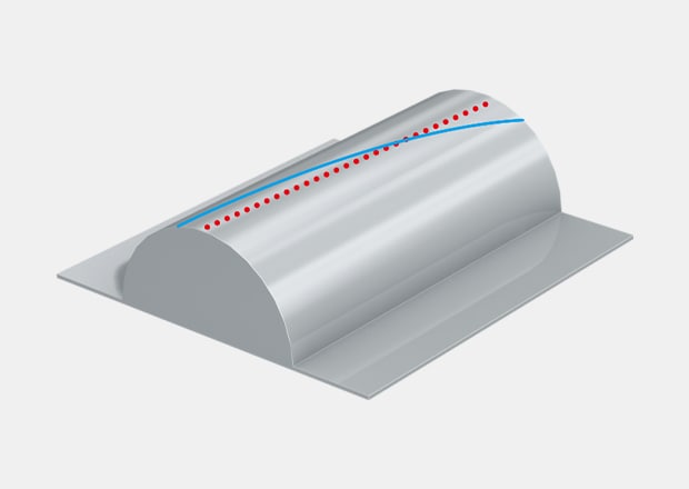
- It is difficult to draw a profile line that passes through the maximum point on a cylinder.
- The stylus moves up and down in an arc centered on the fulcrum of the stylus arm, and the tip of the stylus also moves in the X-axis direction. This produces error in the X-axis data.
Solution to Problems in Undercut Measurement
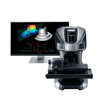
Conventional tools used to measure undercuts have limitations due to the fact that measurement of three-dimensional targets and areas is performed by means of point or line contact. This results in unreliable measurement results. To resolve these measurement problems, KEYENCE has developed the VR-6000 Series Wide-Area Optical Profiler which can accurately capture the 3D shape of an entire target without contacting the surface. It also measures the 3D shape by 3D-scanning the target on the stage in as little as one second with high accuracy. It is capable of instantaneous and quantitative measurement with no errors in the measurement results. This section introduces some specific advantages of the VR-6000 Series.
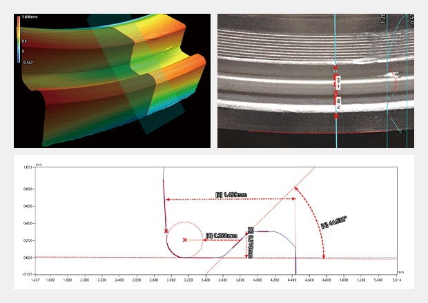
Undercut measurement for a bearing
Advantage 1: Capable of Measuring Small Undercuts With Complex Shapes
The VR-6000 Series measures the entire surface of an object to capture the shape and collect data over a wide area. Because it identifies the entire shape, accurate measurement is possible even for small undercuts in recessed locations that are difficult to trace with a stylus. All measurement data is stored, and the stored data can be compared with other data or with 3D design data.
Conventional measuring instruments require much time and effort to measure undercuts at locations that are difficult to trace with a stylus. However the VR-6000 Series is able to measure them accurately.
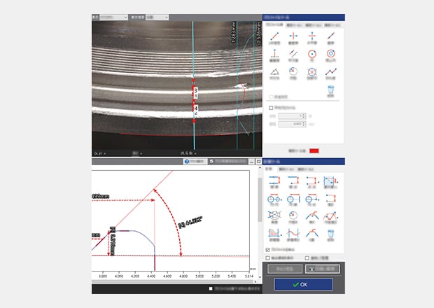
Undercut measurement using tools
Advantage 2: No Variation in Measurement Results
A variety of measurement assist tools allow for profile lines to be drawn anywhere on the part without variation in measurement results. This includes measurement of cylinders and perpendicular profile lines.
The VR-6000 Series is able to quickly and accurately measure undercuts for complex shapes that conventional system struggle with. Once a workpiece has been scanned, its profile (cross-section) can be measured at any location, eliminating the need to re-set the target. This also enables comparisons with past data to check the differences in shape when a workpiece is supposed to have the same shape but was manufactured in a different lot using different materials under different processing conditions.
Summary
The VR-6000 Series can measure 3D target shapes accurately and instantaneously by high-speed 3D scanning without contacting the target. Measurement can be completed in as little as one second even for difficult measurements such as the depth and width of small undercuts or recesses. The VR-6000 Series solves all the problems involved with conventional measuring instruments.
- Because it measures the entire surface, the VR-6000 Series can easily measure undercuts that have complex shapes. The highest points and lowest points can also be measured.
- This eliminates variation resulting from human factors, making true quantitative measurement possible.
- Without the need for positioning or other preparation, measurement can be done simply by placing the target on the stage and pressing a button. This eliminates the need to assign a specialized operator for measurement work, and eliminates variation in measurement values.
- 3D shapes can be measured easily at high speeds with high accuracy. This makes it possible to measure a large number of targets in a short time, helping to improve quality.
- This system also allows comparisons with past 3D shape data and CAD data, as well as easy data analysis such as distribution within tolerances. It can be used effectively for a wide range of purposes including product development, manufacturing trend analysis, and sampling inspections.

Related Downloads

Related Products
Applications
- Chamfer
- Corner Rounding / Fillet
- Bending Radius
- Corner Relief / Undercut
- Taper
- Shank Thread / Underhead Shape
- Tooth Thickness
- Rake Angle
- Metal Burr
- Plastic Burr
- Shear Droop
- Sink Mark
- Solder Fillet
- Weld Bead
- Lead Frame (Lead Lifting)
- Warpage
- Flatness
- Coplanarity
- Surface Waviness
- Surface Area
- Wear
- Bearing Wear
- Die Wear
