3D Optical Profilometers
Efficient Warpage Measurement
-
Tags:
- Electronic Devices , Plastics , Stamping
Measuring instruments used to measure warpage of a surface include dial gauges, profile measurement systems, and coordinate measuring machines. However because warpage is three-dimensional deformation, it is difficult to measure accurately using these conventional measurement methods, which depend on measuring points and lines.
Depending on the target shape and size, there are many locations where warpage cannot be measured accurately using conventional methods, or where measurement itself is physically impossible.
Here we will explain basic knowledge of warpage, measurement methods, problems in conventional measurement, and the latest solution to these problems.
Warpage
Warpage is a term that describes how an object curves or bows. In general, warpage of industrial products refers to curvature of plate materials, and indicates whether the flatness exceeds the specified tolerance values.
Flatness
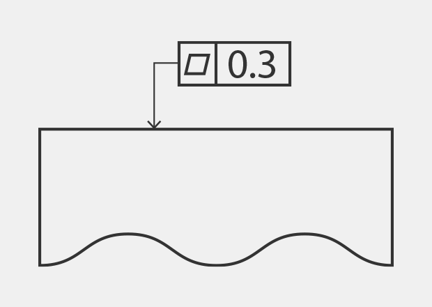
Flatness is defined as the size of the differences between a nominally flat surface and a geometrically correct plane. In drawings, it is indicated as follows.
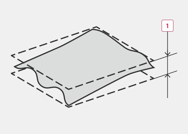
Supposing that the target is sandwiched by two perfectly flat and parallel planes, the distance between those planes is the flatness. In other words, when the tolerance specifies how flat the target surface should be, the most convex part and the most concave part must be within two parallel planes above and below the target surface that are separated by the specified distance.
An image of specifying the flatness tolerance shown in the above drawing is as follows.
-
10.3 mm (0.012″) or less
Causes and Effects of Warpage
There are a wide range of causes and effects of warpage in products and parts, depending on the material and methods of manufacturing and forming. Some examples are given below.
Warpage of Plastic Molded Products
With plastic molding, warpage occurs in molded products due to causes such as differences in shrinkage when the plastic material solidifies, cooling temperature differences in the mold, and material orientation.
With injection molding, warpage may be caused by the time and pressure of injection and pressure hold.
Warpage of Wafers
A wafer is subjected to stress (mechanical stress) during the production processes. In many cases, such stress is not equally applied to top and bottom sides of the wafer, resulting in warpage. Particularly at the polishing process, when stress on the machined surface is large, convex warpage (forward warp) or concave warpage (reverse warp) may occur as a result of residual stress.
Warped wafers affect the yield rate. In addition to causing chip mounting failures, warpage may result in other problems, such as dropped wafers caused by vacuum leakage and suction failure.
Warpage of PCBs
As a result of increasingly compact designs and higher density mounting in electronic components, the reflow method is generally used for mounting of components. However, warpage may occur in the PCBs due to heating at the reflow mounting process.
If warpage occurs in a PCB during the reflow heating process, it may cause lifting of the mounted IC leads, resulting in mounting defects or connection defects.
Even after mounting, heat generated by the power supply during operation may cause PCB warpage that leads to failure of component contacts and product malfunction.
Warpage of Metal Plates
Typical causes of warpage are the heat and residual stress which are applied during pressing and various other types of metal working.
However when flatness is not maintained in sheet material for pressing after cutting by wire electric discharge machining, then this may affect the product shape after pressing. Because warpage may occur in metal materials due to thermal expansion, it is important to carefully consider the temperatures of jigs and forming machines, as well as the material storage temperature.
Importance of and Problems in Warpage Measurement
In addition to the above examples of warpage, there are many cases when warpage occurs as a result of heat or residual stress. To prevent the occurrence of defects and failures and maintain stable quality, it is important to accurately measure the warpage of material before forming, and that of products after forming.
As shown below, a variety of measurement methods are used to measure warpage.
- A method of fastening a dial gauge to an arm and reading the changes in the measured value while tracing the gauge along the target surface.
- A method of using a transparent glass master standard with a flat measurement surface and placing the optical flats in contact with the measurement surface in order to measure the number of stripes (optical interference fringe: Newton’s rings).
- Measurement using a profile measurement system or coordinate measuring machine.
However, warpage measurement using conventional contact-type measuring instruments involves the following problems.
Problems in Warpage Measurement Using a Profile Measurement System
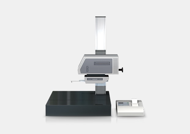
A profile measurement system measures and records the profile of a target by tracing its surface with a probe called a stylus.
In recent years, profile measurement systems have been developed that use a laser instead of a stylus to measure complex shapes by tracing the profile in a non-contact manner. Some models are even able to perform measurement of both the top and bottom surfaces.
Measurement of warpage using a profile measurement system involves the following problems.
- Because the target is measured by tracing along a line, it is difficult to identify warpage.
- It is not possible to identify the conditions of the entire target surface.
- When there are irregularities (mounted chips) on the measured surface as there are on a PCB after components are mounted, it is difficult to detect whether or not there is warpage of the PCB itself.
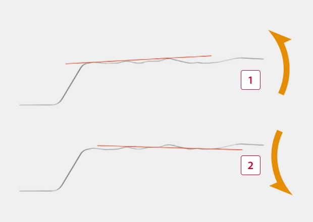
- Setting a reference plane using lines is difficult, and as a result measurement error may occur (see figure).
-
1Upward slope
-
2Downward slope
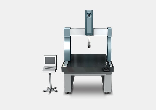
Problems in Warpage Measurement Using a Coordinate Measuring Machine
In general, when measuring warpage using a coordinate measuring machine, it is necessary for the probe to contact four or more corners on the measured surface of the target.
In case of a plate for example, generally six to eight points are measured. When the measurement area is large, measurement accuracy can be improved by increasing the number of measured points to collect more measurement data.
However, measurement of warpage involves the following problems.
- Because it is necessary to measure only by means of point contact, it is difficult to identify the entire shape of the target.
- Measuring more points to acquire more measurement data requires much time, and it is still not possible to identify the detailed shape of the entire target.
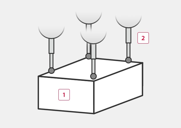
-
1Target
-
2Probe
Solution to Problems in Warpage Measurement
Because conventional contact-type measuring instruments measure shapes using lines or points, they cannot measure the entire surface of the measurement target. Even when more points are measured to acquire more measurement data, many man-hours are required, and it is still not possible to identify warpage and other elements of the detailed shape for the entire target. In many cases, warpage measurement requires experience, knowledge and skill. Securing the necessary measurement personnel is a major problem, as is variation in the measured values between different operators.
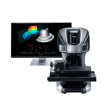
To resolve these measurement problems on the site, KEYENCE has developed the Wide-Area Optical Profiler VR-6000 Series.
The VR-6000 Series accurately captures the 3D shape of an entire target surface without contacting the target. Without requiring any strict positioning, a 3D scan of the target on the stage can be completed in as little as one second, for high accuracy measurement of the 3D shape. This allows quantitative measurement and inspection to be instantaneously performed without variation in the measurement results. This section introduces some specific advantages of the VR-6000 Series.
Advantage 1: Scanning the Surface Shape Instantly Identifies the Entire Target's Shape
For example, drawing is a pressing process that involves a high level of difficulty in deciding the optimal processing conditions. Unexpected deformation of materials can occur due to mechanical stress. Care must be taken to prevent warpage and other forming errors.
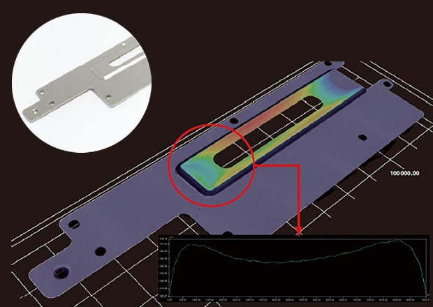
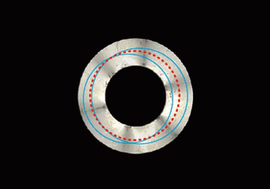
Warpage shape and profile measurement of a drawn part with the VR-6000 Series
With the VR-6000 Series, you only need to place the target on the stage and scan it. The 3D shape of the target can be captured and no positioning is required.
As the target height can be displayed in colors and profile measurement is possible at any part of the target, it is possible to visualize and identify the locations and precise numerical values of shape defects. This makes it possible to smoothly identify and correct the causes of defects caused by the molds, dies, and forming conditions.
Because the shape data is measured quantitively, it is possible to easily control warpage based on the tolerance values or to use the measurements for trend analysis.
Advantage 2: Non-Contact, High-Speed Scanning That is Completed in as Little as One Second Makes It Easy to Identify Warpage of the Entire Target
Warpage of PCBs may occur due to heating at the reflow mounting process and may cause lifting of leads or other problems. However, with conventional contact-type measuring instruments, it is extremely difficult to measure warpage of the entire PCB after surface mounting.
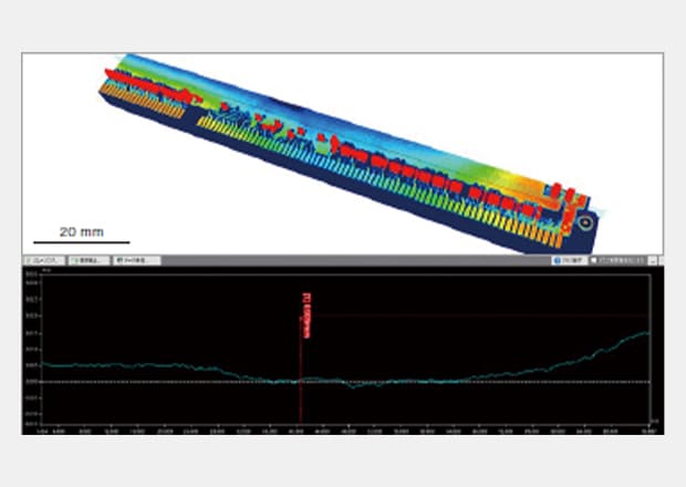
Warpage measurement and inspection of a surface mounted PCB with the VR-6000 Series
With the VR-6000 Series, it is possible to scan the entire shape by non-contact means in as little as one second simply by placing the PCB with mounted components on the stage. In addition to identifying warpage of the entire PCB, this allows instantaneous identification of mounted component lifting as well. Because profile data can also be obtained at the locations of defects or at any part of the target, the VR-6000 Series can quickly acquire detailed data of shape changes.
Careful positioning of the target is not required. Simply by placing the target on the stage, the image is corrected automatically to enable fast and easy quantitative measurement and inspection.
Advantage 3: Capable of Quantitative Comparison and Analysis of Multiple Sets of Measurement Data
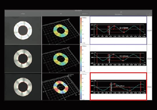
The VR-6000 Series can measure the 3D shape of the entire target by 3D-scanning the target surface in as little as one second. This makes possible quantitative measurement of a large number of targets in a shorter time than with conventional methods. In this way, multiple sets of efficiently collected measurement data can be displayed in lists, and the same analysis contents can be applied to all data sets at the same time.
Differences in the shape data of multiple targets can be confirmed at a glance. This makes it possible to perform batch analysis of flatness using multiple data sets, and to easily perform quantitative evaluation of how much an NG part is warped compared to an OK part.
Conventional Instruments
With a conventional instrument, accurate comparison is difficult due to differences in the measurement locations and variation in the measured values.
The VR-6000 Series
With the VR-6000 Series, measurement is performed instantaneously without the need for positioning. Quantitative comparison and analysis of multiple sets of measurement results can be performed easily by displaying them side-by-side and applying the same analysis contents to all measurement results at the same time.
Summary: Dramatic Improvement and Higher Efficiency in Difficult Warpage Measurement
The VR-6000 Series can instantaneously measure warpage and other accurate 3D shapes using high-speed 3D scanning without contacting the target.
- Because the entire surface is measured, it is possible to identify all locations of warpage on the target, and to perform profile measurement at any desired part.
- No positioning is required. Simply place the target on the stage and press a button to complete measurement.
- 3D shapes can be measured easily at high speeds with high accuracy. This makes it possible to measure a large number of targets in a short time.
- Multiple sets of measurement data can be easily and quantitatively compared and analyzed.
In addition, by setting a tolerance for flatness, it is possible to easily judge OK/NG products, and to analyze NG products based on the data. The VR-6000 Series makes it possible to measure warpage of targets such as surface mounted PCBs that could not be measured before. It enables fast and accurate warpage measurement, a dramatic improvement in the efficiency of measurement work, and seamless data analysis.

Related Downloads

Related Products
Applications
- Chamfer
- Corner Rounding / Fillet
- Bending Radius
- Corner Relief / Undercut
- Taper
- Shank Thread / Underhead Shape
- Tooth Thickness
- Rake Angle
- Metal Burr
- Plastic Burr
- Shear Droop
- Sink Mark
- Solder Fillet
- Weld Bead
- Lead Frame (Lead Lifting)
- Warpage
- Flatness
- Coplanarity
- Printed Circuit Boards (Warped PCBs)
- Surface Waviness
- Texture (Surface Texture)
- Sheet Uneven Surface (Textured Sheets)
- Surface Area
- Wear
- Bearing Wear
- Die Wear
- Heat Treatment Deformation
- Strain
- Charpy Impact Test
