


Manchester encoding method
This method expresses 0 s and 1s in data as rising and falling edges. In this method, the average value of encoded signals is always the same, regardless of the signal status.
AS-i
This section explains AS-i.
Overview
The AS-i network standard was developed in 1990 to simplify wiring connections for sensors and actuators. Its official standard name is Actuator Sensor Interface, but the abbreviated name, AS-i, is used. Power is supplied via a single two-wire cable, which helps simplify wiring.
Wiring Method and Communication Protocol
Wiring method
The network is wired using special yellow cables each consisting of only two wires that also supply power.
AS-i transmits signals at a transmission rate of 167 kbps by superimposing a sine waveform on the power voltage. Up to 62 slave stations can be communicated with, supporting various network topologies such as tree, bus, star, and ring. The maximum wiring length is 100 m (328.1′), or 300 m (984.3′) when repeaters are used, requiring no terminating resistor.
Using the special cables and special contact blades eliminates wiring work, such as cable sheath removal and cutting.
Wiring image
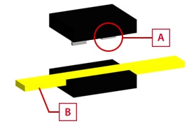
Contact blade
Special cable
A device can be wired by placing the cable between the two parts of the contact blade.
Communication protocol
The standard AS-i protocol is supported. This protocol provides excellent noise immunity by converting data into Manchester II codes and sine waveforms and guarantees a cycle time of 10 ms or less when using 62 slave stations.
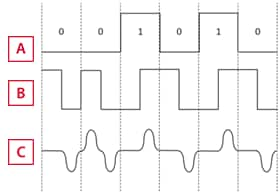
Data
Manchester encoding
Conversion into a sine waveform
Characteristics
AS-i sends and receives data using the master/slave method.
Designed for transmission of small numbers of I/O signals, AS-i sends and receives data via periodic polling from the master. Data can be collected automatically from connected compatible devices without using configuration software. AS-i version 2.1 is capable of detecting abnormalities, such as short circuits and overloads of auxiliary power supply, in addition to communication errors.
- Company, product, and network names mentioned on this page are either trademarks or registered trademarks of their respective companies.
- Note that some information, such as applicable standards and specifications, may have changed since this page was published.
November 2015


