
Vision Systems
This page introduces KEYENCE’s lineup of vision systems in addition to the supported networks and connection examples.

- Vision system lineup
- Connection example
- Network example
- Supported networks
- Typical connection example
Vision system lineup
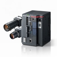
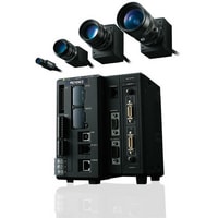
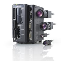
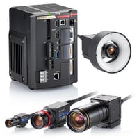
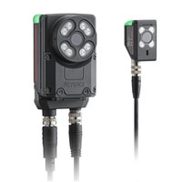
Vision systems
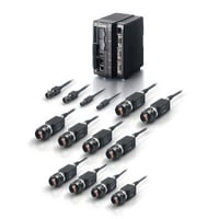
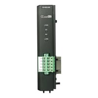
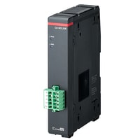
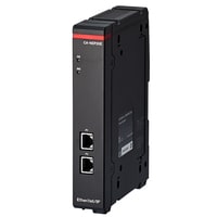
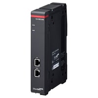
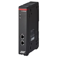
Communication unit

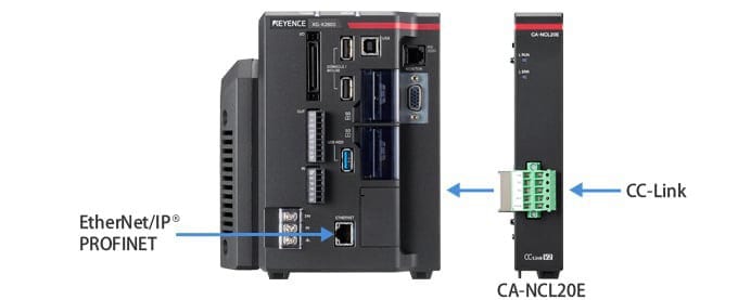
Connection example
The controller’s internal communication interface can be used for EtherNet/IP®, PROFINET, or RS-232C connections with the XG-X, XG-8000, XG-7000, CV-X, and CV-5000 Series. A communication unit must be used for CC-Link connections.
Connecting the IV Series to an EtherNet/IP® or PROFINET network requires a dedicated cable.
Network example
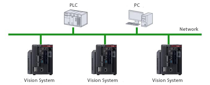
- A network-compatible unit or board is required for PLCs and PCs.
- A 1:1 connection is used for connections via RS-232C.
Supported networks
| Series | Field network | Other communication functions | |||
|---|---|---|---|---|---|
| EtherNet/IP® |
CC-Link | PROFINET |
Ethernet TCP/IP* |
RS-232C* RS-422A/ 485 |
|
| Customizable Vision System XG-X Series |
Field network
✓
|
✓
(CA-NCL20E) |
✓
|
Other communication functions
✓
|
✓
RS-232C |
| Customizable Vision System XG-8000 Series |
Field network
✓
|
✓
(CA-NCL10E) |
✓
|
Other communication functions
✓
|
✓
RS-232C |
| Customizable Vision System XG-7000 Series |
Field network
✓
|
✓
(CA-NCL10E) |
✓
|
Other communication functions
✓
|
✓
RS-232C |
| Vision System CV-X Series |
Field network
✓
|
—
|
✓
|
Other communication functions
✓
|
✓
RS-232C |
| Vision System CV-5000 Series |
Field network
✓
|
✓
(CA-NCL10E) |
—
|
Other communication functions
✓
|
✓
RS-232C |
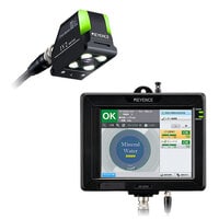
| Vision Sensor with Built-in AI IV3 Series |
Field network
✓
|
—
|
—
|
Other communication functions
—
|
—
|
| Vision Sensor with Built-in AI IV2 Series |
Field network
✓
|
—
|
—
|
Other communication functions
—
|
—
|
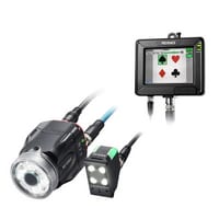
| Vision Sensor IV Series |
Field network
✓
|
—
|
✓
|
Other communication functions
—
|
—
|
PLC link connectivity of PLCs made by various other manufacturers is possible via RS-232C/Ethernet.
Typical connection example
Connecting to a network makes it possible to collect and manage various information from vision systems. This allows for the construction of information systems for saving image-based history, PLC-based calculations, changeovers, production management, and more.
The following example includes a network-connected vision system.
Centralized management and changeovers through PLC-based control of peripheral equipment
Alignment can be performed by collecting changeover information from network-connected PCs and vision system measurement results in the PLC. Control of peripheral equipment is also possible, including PCB position adjustments according to the position of targets, and using the touch panel to change the amount of adhesive to be applied.
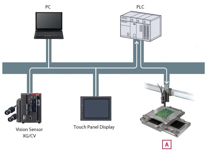
Dispenser positioning