IO-Link
This section explains IO-Link.

- IO-Link Overview
- IO-Link Interfaces and Communication Data
- Features and Original Benefits of KEYENCE’s IO-Link
IO-Link Overview
What is IO-Link?
IO-Link is an I/O connection technology that connects sensors and actuators via simplified wiring and allows them to communicate with programmable logic controllers (PLCs) and human–machine interfaces such as touch panel displays. IO-Link compatible devices, such as sensors and actuators, are connected to an IO-Link master using a single cable to communicate with a PLC collectively, which simplifies data reception and device setting.
IO-Link was released in 2006. It was standardized by the international standard IEC61131-9 in 2013 after PROFIBUS & PROFINET International (PI), which promotes technical standards such as PROFINET, established IO-Link Consortium, a dedicated committee for IO-Link in 2010. Since then, the introduction of IO-Link has accelerated all over the world, especially in advanced facilities in Europe and Asia. Recently, an increasing number of companies have introduced IO-Link in Japan to dramatically reduce the amount of wiring work and improve operation efficiency.
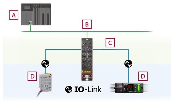
PLC, etc.
Industrial network
IO-Link master
IO-Link compatible devices
What is IO-Link master?
IO-Link masters are equipment that can connect multiple IO-Link compatible devices such as sensors and actuators. IO-Link compatible devices are generally connected using unshielded three- or five-wire cables and each cable can be extended up to 20 m.
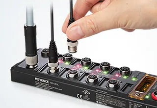
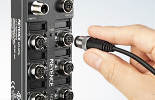
Typical IO-Link masters have a housing with multiple M12-round connector ports (jacks). Each device can be connected by simply inserting a single cable that allows for high-speed data communication between the IO-Link master and the device.
IO-Link masters also automatically save device parameter settings, which makes it possible to recover from problems, such as device malfunctions, quickly by simply replacing faulty devices.
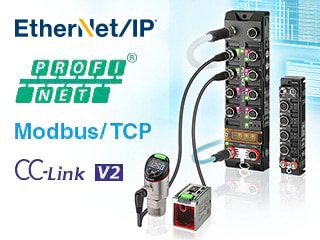
By supporting typical industrial networks such as EtherNet/IP®, Modbus/TCP, PROFINET, and CC-Link version 2, IO-Link masters can be easily connected to PLCs and human–machine interfaces such as touch panel displays.
IODD file
Vendors of IO-Link compatible devices, such as sensors and actuators, prepare IO Device Description (IODD) files that contain information such as parameters. IODD files contain information about the manufacturer, model, parameters, and other necessary information. This device information and parameters can be automatically loaded by simply connecting a device to the IO-Link master. Settings can be easily written to connected devices using parameters obtained from IODD files.

IO-Link Interfaces and Communication Data
IO-Link wiring method
A device can be connected to a IO-Link master by simply inserting a single unshielded three- or five-core cable that both supplies power and transmits signals.
M5, M8, and M12 connectors are specified for IO-Link, and M12-round connectors are commonly used for the IO Link masters.
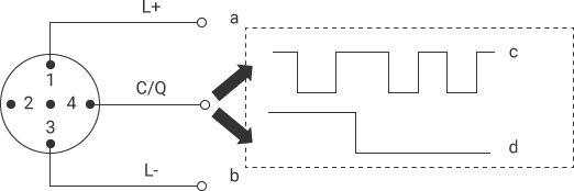
- a
- 24 VDC (200 mA max.)
- b
- Ground
- c
- IO-Link mode
- d
- Standard I/O mode
Types of operation modes and communication data
The signal line (C/Q) of IO-Link connectors has two operation modes: IO-Link mode and I/O mode, which handles signals as standard digital I/O signals. The mode can be selected according to the device that is connected.
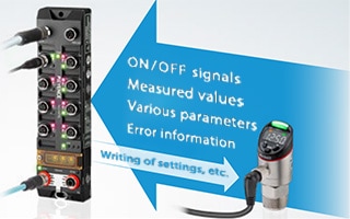
In IO-Link mode, the following data types can be communicated between the master and devices. Bidirectional communication allows for symptom monitoring, predictive maintenance, and quick troubleshooting.
Process data (cyclic)
This is data communicated in a cycle without using special programs. The contents of process data differ depending on the IO-Link device, but it usually contains the current value, output signal, and error status of a sensor.
Device data (non-periodic)
This data is communicated by the IO-Link master at arbitrary timing. Parameter values can be read from and written to this data. IO-Link device statuses can also be read out from this data.
Event data (non-periodic)
When the master receives data containing error messages, such as short circuits, disconnection, contamination, and temperature abnormalities detected by the device, or maintenance information, it transmits the data to host equipment such as PLCs.
Port type
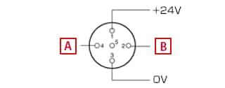
M12 connectors used for IO-Link have two port classes: class A and class B. The connector pins (pin assignment) of class A and B are used differently. Devices are connected using corresponding connectors.
Class A (port class A)
IO-Link communication or digital input
Digital input or digital output
With class A, there are three wires: the signal line (C/Q), L+, and L-, which can supply power to an IO-Link compatible device at 24 V. The maximum current capacity supplied by L+ is 200 mA. If the connected device consumes a small amount of current, such as most sensors, data communication and power supply can be performed using a single cable.
Class B (port class B)
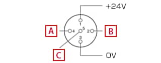
IO-Link communication or digital input
Additional +24 V
Additional OV
When power is supplied to a device that consumes a large amount of current, such as actuators and solenoid valves, the amount of current supplied by class A may be insufficient. In these cases, the five-wire class B can be used. With this standard, currents up to 4 A can be supplied over UA+ and UA- without the need to increase the number of cables.
Benefits of IO-Link
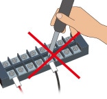
Conventional wiring work performed on terminal blocks in relay boxes required a lot of time and effort, and presented the risk of incorrect wiring. IO-Link performs both power supply and data transmission by simply connecting a device, such as a sensor or actuator, to the master using a single cable. IO-Link has the following advantages in wiring, connection, and communication.
- A device can be connected using a single cable with no tools, which dramatically reduces the amount of wiring work and risk of incorrect connection. Faulty points are also easily identified.
- Information and parameters of connected devices can be obtained from their IODD files, allowing for quick configuration. Multiple data communication methods are available.
- The cable length can be extended up to 20 m (65.6′), so wiring is highly flexible.
- In IO-Link mode, statuses and problems can be checked at various timing using bidirectional communication between master and devices, which is useful for status monitoring, predictive maintenance, and quick troubleshooting.
- The IO-Link mode has three communication speed standards: COM1, COM2, and COM3. The speed is usually switched automatically according to a connected device, which ensures that the transmission speed required for stable communication is used without any manual configuration. (COM1 = 4.8 kbps, COM2 = 38.4 kbps, COM3 = 230.4 kbps)
Features and Unique Benefits of KEYENCE’s IO-Link
KEYENCE offers the network communication module NQ Series, which is an IO-Link master along with a wide lineup of IO-Link compatible sensors. These devices are designed for convenience and ease of handling in addition to functionality and reliability, based on feedback from operators at manufacturing sites all over the world. We have improved functions to meet on-site needs in both hardware and software.
One feature of the NQ Series is that it supports IO-Link, which is increasingly being used at plants outside of Japan, so that it can be introduced and operated easily at plants in Japan.
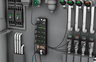
Significant reduction in start-up time. Easy, space saving connection
Sensor wiring can be completed by simply inserting an M12 connector without using tools. This reduces the wiring work required with conventional relay boxes to approximately one sixtieth. The NQ Series also eliminates the work required to design and create covers and other protective countermeasures because it has a slim, highly durable housing. In addition to simplified wiring, the NQ Series reduces the time required for various wiring work, while saving space on control panels.

Wiring end treatment
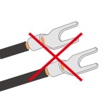
Y-shaped terminal processing
Marking tube attachment
Screw tightening
Quick and correct configuration with Japanese indications
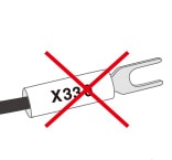
Manufacturer names, device names, and parameters obtained from typical IODD files of connected devices are described in English. This requires users to check with user’s manuals of sensors to identify which setting each parameter corresponds to.
The NQ Series automatically recognizes KEYENCE’s IO-Link compatible sensors when they are connected. Manufacturer names, device names, and parameters obtained from IODD files can also all be localized into Japanese when they are displayed. This saves the time and effort required to verify and check English parameter names, while also preventing incorrect parameter settings caused by misunderstanding.
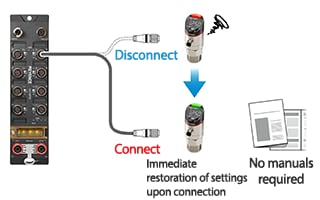
The data storage function allows for quick recovery when problems occur.
Settings and parameters for each sensor are backed up with the data storage function of the IO-Link master NQ Series module. For example, when a connected sensor malfunctions, communication can be restored by simply replacing the faulty sensor with a new one. Problems such as temporary stoppage and sensor malfunctions can be identified instantaneously with the master and PLC, and no time or effort are required to set up an alternate sensor, which significantly reduces downtime.
Setup, data collection, and remote monitoring with the NQ Sensor Monitor software (free of charge)
The PC software, NQ Sensor Monitor, is available to download for free to use with the NQ Series. By simply installing it on a PC and connecting the PC to the NQ Series, a variety of operations can be performed easily, including batch setting of multiple sensors, data collection from sensors, output to CSV files, automatic transfer to Excel spreadsheets, and remote monitoring.
Additionally, symptoms can be monitored by managing numeric data collected from connected sensors, which allows for predictive maintenance in which abnormal symptoms are detected early so that action can be taken before problems occur.
The NQ Series can also connect the IO-Link master directly to a PC, without using a PLC, with low latency, which allows use of a PC to monitor devices in real time on site and change device settings remotely.
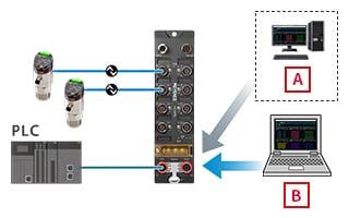
Check from office
Check on site