Basics of Appearance Inspection
Principles and Optimal Settings for Visual/Stain Inspections
Appearance inspections are performed to check foreign matter, scratches, and defects on the surface of parts and products. In general, the following inspection contents fall under the scope of appearance inspections.
- Foreign matter on food containers: Foreign matter inspection
- Dirt on cloth: Dirt inspection
- Scratches on metal/resin parts: Scratch inspection
- Chipping and burrs occurring during resin/rubber molding: Defect inspection
- Checking for LEDs not lit: Defect inspection
Conventionally, appearance inspection was performed visually. In recent years, however, image processing systems have been introduced along with factory automation (FA). This section introduces the basic principles of appearance inspection.

Principles behind the stain inspection tool
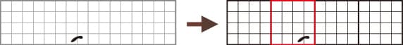
Segment
The machine vision system detects changes in intensity data from a CCD image sensor as stains or edges. However, it takes an enormous amount of time to process every pixel, and noise may affect inspection results. Therefore, the machine vision system uses the average intensity of a small area consisting of several pixels. In the CV-X Series, this small area is called a “segment”, and the average intensity of these segments is compared to detect stains.
Algorithm of the stain inspection tool (Comparison and calculation methods of segments)
This section explains the algorithm of the stain inspection tool equipped on the CV-X Series.
Detection principle (When the detection direction is specified as X)
- The stain inspection tool measures the average intensity of specified areas (segments) and shifts them by 1/4 the area of a segment size.

- It determines the difference between maximum and minimum intensities of 4 segments, including a standard segment (① 95 in the figure below). The difference is considered the stain level of a standard segment.
- When the stain level exceeds the present threshold, the standard segment is counted as a stain. The number of times the preset threshold is exceeded in a measured area is called the “Stain Area”. The process repeats to constantly shift the standard segment within the measured area.


In the subsequent processes, steps (1) to (3) are repeated while the target segment is shifted by the travel range within the area.
When X and Y directions are specified as the detection direction
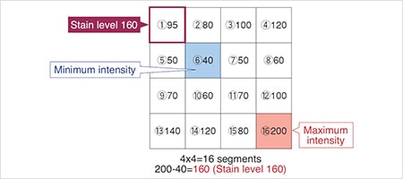
The difference between the maximum and minimum intensity of 16 segments in both the X and Y directions are calculated using the standard segment as a reference.
It is possible to detect smaller and more subtle intensity changes (stains) by comparing 16 segments in total, not just 4 segments in the X direction.
Summary of principle behind the stain inspection tool
The stain inspection tool is a tool that detects change points of density as scratches and dirt compared to the surrounding every small unit of several pixels called "segment". By processing for each segment, it is possible to realize high speed while reducing the influence of noise, and by comparing with surrounding segments from multiple candidates, "small scratches" and "thin stains" etc. which were difficult to detect conventionally It can now be detected.

Optimal settings for the stain inspection tool
Optimal segment size
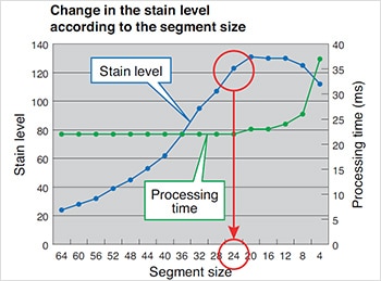
This section explains how to set the stain inspection tool appropriately. It is possible to optimize the detection sensitivity and processing time by adjusting the segment size.
The graph on the right shows changes in the stain level and processing time according to the segment size (with KEYENCE’s CV-X Series).
When the segment size is almost the same as the target size, the stain level is at maximum. This means that the detection sensitivity and processing time can be optimized by adjusting the segment size to the actual target size.
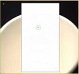
Inspection image
Optimal segment size = Stain size (mm) × No. of pixels in the Y direction / Field of view in the Y direction (mm)
Ex.) When the stain size is 2 mm2 and field of view is 120 mm2, and a 240,000-pixel camera is used (480 pixels in the Y direction),
2 × 480 ÷ 120 = Segment size 8
Segment shift / Gap adjustment according to the image
The stain inspection tool parameters, Segment shift and Gap adjustment, determine the amount of segment shift for intensity comparison. Small flaws and subtle stains, which have different features, can be detected by adjusting these parameters.
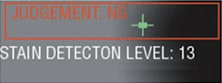
Stain level = 13

Stain level = 47
The gradual intensity change is increased by enlarging the gap adjustment.
In order to detect small flaws, it is necessary to finely compare segment intensities by setting both Segment shift and Gap adjustment to small values. On the other hand, in order to detect subtle stains, it is necessary to broadly compare segment intensities by setting both parameters to large values. In this way, the appropriate settings, which correspond to the type of flaw or stain, lead to stable detection.
Summary of optimum setting for Stain mode
Adjustment of the optimum segment size and travel range/comparison interval setting allows optimum inspection of targets. You can ensure optimum settings by adjusting the segment size to be the same as the size of the stains/flaws; and determine the travel range and comparison interval based on the size and shade level of the stains/flaws.
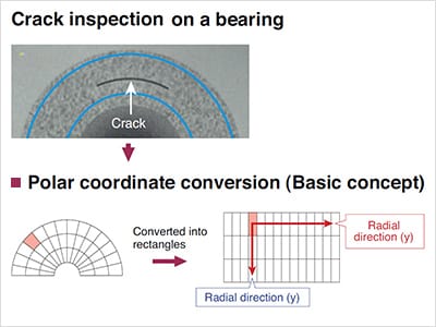
Stain Inspection on Circular Workpieces
Many kinds of circular workpieces, such as PET bottles, bearings or O-rings require a circular area for visual inspection.
When the CV-X Series is searching a circular area, the program is performing polar coordinate conversion. In order to detect stains, it converts a circular window (inspection segments) into rectangles and compares the segments’ intensities in both circular and radial directions.
Useful pre-processing filters for the stain inspection tool
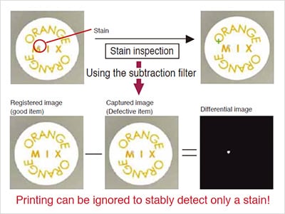
Subtraction filter: When printing should be ignored to detect only a stain
If only intensity changes are measured without any reference, it is impossible to distinguish between stains and proper printing. Printing with more contrast than a stain is subsequently detected as a flaw.
In pre-processing, a proper image is registered and then compared with the current image with the subtraction filter. Then, the average intensity of the filtered image is compared in 256 levels. This enables stain inspection of workpieces with complicated printing.
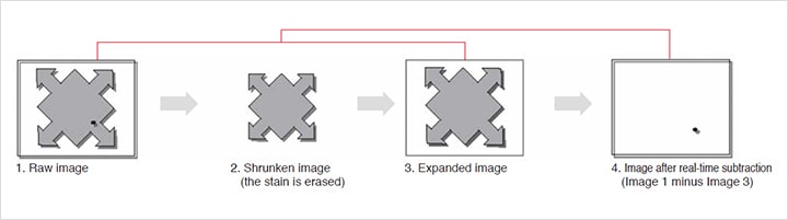
Real-time subtraction filter
The real-time subtraction filter extracts only small defects by differentiating the original image from an image using the Expansion and Shrink filters. With this filter, you neither have to specify the inspection area nor adjust for the displacement of the target (good for complicated shapes). You can inspect targets with complicated shapes by adding one simple setting adjustment.
Summary of Visual/Stain Inspection
Note the following 3 points for optimal use of the stain inspection tool:
- Adjust the segment size to the stain size
- Set segment shift / gap adjustment according to the stain size or intensity
- Use pre-processing filters according to the workpiece conditions
However, clear images are definitely important to take full advantage of the machine vision system's features.
The next topic is the principle and applications of dimension measurement (edge detection). Edge detection can be used for various applications such as position, width, pitch, and angle measurements. Let's look at the algorithm and applications of edge mode.


![A Technical History of Image Processing Vol.1 [Camera]](/img/asset/AS_46814_L.jpg)
![The Latest Image Processing Applications [Transportation Industry]](/img/asset/AS_71759_L.jpg)

![The Latest Machine Vision Inspections [Food and Medical Industries]](/img/asset/AS_72814_L.jpg)