Position Correction
Understand the position adjustment system to accurately inspect moving targets
Position Adjustment is usually required when inspecting objects on a production line. This function combines the Adjustment Origin window (the inspection frame that calculates misalignment) and the Adjustment Target window (the inspection frame that is adjusted).

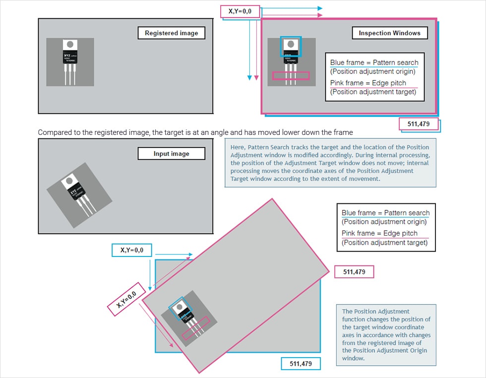
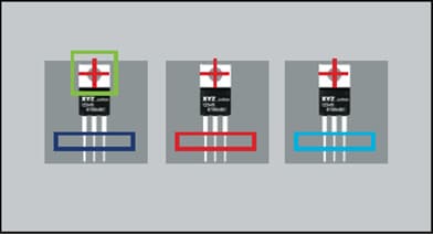
Position adjustment principle - coordinate axes (Batch position adjustment using Pattern Search)
Example: When the deviation from the reference image of the heat dissipation plate (blue frame) of a three-pin terminal is used as the position correction data for the window (pink frame) for the pitch inspection of the lead section (pink frame).
POINT
The Position Adjustment function involves internal processing that changes the coordinate axes of the Adjustment Target window. Areas of the Adjustment Origin window and the Adjustment Target window appear to be the same when viewed on the monitor, but have different standards of coordinate point data output as measured values.
When calculating between windows that have different coordinate axes, measured absolute value data uses the top left of the CCD as the point of origin.

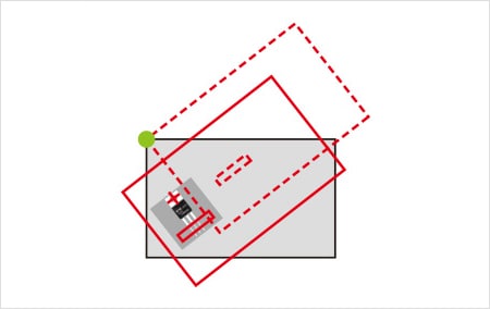
Position adjustment principle - center of rotation(Batch position adjustment using Pattern Search)
Position adjustment involves measuring the extent to which the target window must be repositioned in relation to the registered image. In the case of angle data, the point that is used as the center point to change the angle is extremely important. This point is called the center of rotation. When X and Y coordinates and angle are adjusted via a pattern search, the center point of the pattern becomes the center of rotation.
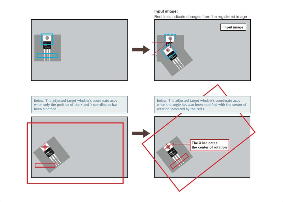
If only the angle, and not the center of rotation, is specified, the center of rotation will revert to the point of origin (i.e. the top left corner will be set as 0,0), and the coordinate axes and target window will be misaligned as shown by the red dashed frame. When adjusting the angle, the center of rotation must be taken into consideration. The final position of the position adjustment target window will change greatly according to the point used as the center of rotation for angle adjustment.
POINT
To perform position correction for an angle, you need to consider the rotation center point. In angle correction, the result of the position correction target window varies greatly depending on the rotation center point that is selected. When the coordinates detected by the Pattern search for angle measurement are used, the angle is corrected properly. When the angle is corrected based on calculation, it can also be corrected properly as long as there is understanding of not only the angle but also the rotation center point to be used for the correction.
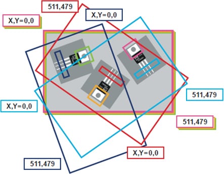
Position adjustment principle - individual position adjustment using multiple pattern search tools
Inspecting three identical targets simultaneously.Register one pattern in Pattern Search and set the number detected to 3 in order to track three patterns at the same time.Three inspection windows(dark blue,red,and light blue)create edge pitch frames on their respective leads.
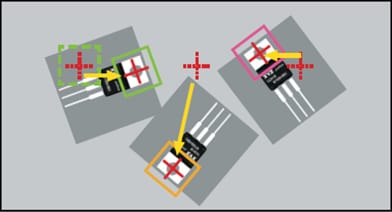
Even if all three move freely.they will be assigned an order from left to right if they are in ascending order on the X axis. The yellow arrows indicate the extent of adiustment from the standard position.
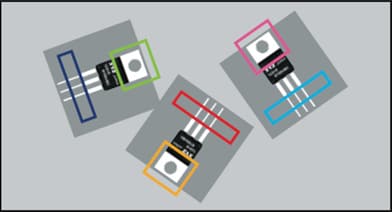
The Position Adjustment value of the dark blue frame is taken from the green frame.the Position Adjustment value of the red frame is taken from the yellow frame,and the Position Adjustment value of the light blue frame is taken from the pink frame.The coordinate axes of the dark blue,red,and light blue frames are shown in the image on the right.
Using KEYENCE's CV Series,it is possible to perform position adjustment between individual windows(individualadjustment),in addition to specifying windows at the same time(batch adjustment).
The four process steps described above make it possible to perform highly accurate edge inspections that are less effected by fluctuations in illumination intensity and other such disturbances. When using the Position Adjustment method, even if there is only one adjustment origin pattern, target windows must be created using a pattern search that detects the position of individual targets.
Summary of the method to inspect a moving target properly by understanding position correction
The following points are the basics of position correction.
- Position correction is the process of passing the difference in the detected position between the reference image and input image in the correction source window to the correction target window as a change in the coordinate axes.
- To perform angle correction, you need to set items with consideration for the rotation center point.
- When performing position correction based on several detection results, you need to consider that the coordinate axes are different in each of the correction target windows and set the area at the respective locations in the correction target windows although the correction source pattern is the same.
[Reference] The first requirement for accurate position correction is accurate inspection of the correction source. For methods of accurate pattern search/edge position setting, refer to the topics Basics of dimension inspection and Basics of position detection.
The next topic is image enhance filters. There are various image enhance filters such as expand and averaging filters, which are useful for stabilizing measurement processing. Using these filters properly requires basic knowledge of their principles. Let's look at the principles and applications in detail.


![A Technical History of Image Processing Vol.1 [Camera]](/img/asset/AS_46814_L.jpg)
![The Latest Image Processing Applications [Transportation Industry]](/img/asset/AS_71759_L.jpg)

![The Latest Machine Vision Inspections [Food and Medical Industries]](/img/asset/AS_72814_L.jpg)