Positioning/Alignment
Positioning/alignment
Positioning/alignment is another process for which image processing has been introduced, alongside inspections for quantity and presence of parts and products, appearance (foreign particles, flaws), and dimensions (length, diameter). Positioning/alignment using image processing systems has been introduced for a variety of purposes:
- Positioning of glass substrates
- Measurement of misalignment of labels or barcodes
- Checking the orientation of IC chips
- Checking for misaligned lids on food containers
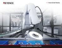
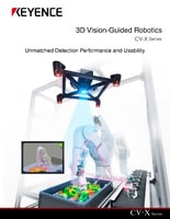
- Position control of machine tools (Vision-guided robots)
This section introduces the basic principles and specific applications of positioning and alignment using image processing.

Basic principle of positioning/alignment for detecting position using image processing
To achieve quick and reliable positioning
To improve the efficiency of production processes, it is necessary to instantaneously detect the positional relationship between the target and machine tool or table and control the system carefully. Poor detection accuracy may lead to defective workpieces. If there is a time lag between detection and control, productivity may decrease. Accurate and quick positioning/alignment is essential for factory automation (FA). Image processing has been increasingly used to achieve it.

Problems in positioning/alignment

Production of LCD panels requires high-accuracy positioning for processes such as glass or film lamination. Although image processing systems have become common in recent years, they had several problems:
- Positioning using image processing systems required too much time and labor for calibration.
- The process functioned as a black box, so it was difficult to add functions and the process lacked versatility.
- Expert knowledge was needed to achieve high-accuracy and high-speed positioning.
- Positioning could not satisfy the required accuracy so the uses were limited.
In recent years, these problems have been overcome owing to Auto-calibration, which completes calibration automatically, and improved accuracy of the alignment for guiding the system to an accurate position.
Flow of positioning using image processing
The first important point is to understand the flow of positioning/alignment that takes advantage of image processing. There may be some variations in the flow depending on the image processing system. This section introduces the basic flow of positioning using KEYENCE's “XG-X Series” with an example of glass lamination.
Auto-calibration
Detect the position of an alignment mark by pattern search (search processing) or other method and calculate the stage axis direction and rotation center position.
Reference position registration
Register the destination to which the target will be moved.
Alignment
Measure the position of the target and calculate the amount of correction to reach the reference position.
Positioning
Feed back the calculated position information to a PLC or other host system and control the stage to perform positioning.

Advantages of positioning using image processing
Introducing image processing systems to positioning/alignment offers multiple advantages:
High-accuracy position detection through pattern search
Pattern search (search processing) is a technique that is indispensable for positioning/alignment using image processing. Pattern search automatically detects reference images or patterns (marks), known as alignment or positioning marks. Using lens distortion correction and filters improves the accuracy of position detection.


Before correction

After correction

Before correction

After correction
Auto-calibration for improving takt
Conventional coordinate-based position control had problems such as misalignment of the target and table and detection accuracy, which prevented ideal detection of position/angle. In recent years, the accuracy of the auto-calibration has improved greatly owing to advances in pattern search (search processing) technology. Automatic high-speed high-accuracy calibration is now possible, resulting in improved takt.
Accurate control supported by high-accuracy detection using image processing
Alignment marks can now be detected with high accuracy by using high-pixel-count machine vision and improved image processing technologies. ShapeTrax is KEYENCE's profile search technology which provides the highest accuracy in the industry. It allows position detection with an accuracy of 0.025 pixels for both linearity and repeatability.

In addition to detecting alignment marks, position detection can be achieved flexibly according to the needs of each application even without alignment marks. Methods to achieve this include detection of a virtual intersection at the corner of a PCB or positioning based on a wafer notch.

Detection of a virtual intersection at the corner of a PCB

Positioning based on a wafer notch
Positioning/alignment achieved with ultra-high-pixel-count cameras
KEYENCE offers ultra-high-pixel-count cameras with 21 megapixels that provide the best solution in the industry. Commonly-used cameras with fewer pixels such as 0.3 or 2 megapixels have the problems shown below. Ultra-high-pixel cameras can eliminate these issues.
Have you ever suffered from these problems?
Products with many rounded sections cannot be detected stably because of unstable detection of corners.
Conventional

When a rounded surface is large, the straight section is too short to detect the corner stably.
Some products have no straight section to use for detection.
When a 21 megapixel camera is used to capture the entire image of the product
From now on

The entire image of the product can be captured while conventional accuracy is maintained.
This allows high accuracy detection of the profile of the entire shape, even when the product has a complex shape.
When a 21 megapixel camera is used to capture the entire image of the product, even complexed profiles can be detected with high accuracy. This ensures stable and accurate alignment of products regardless of their shapes.
Changeover requires lot of labor because different products are manufactured on the same line.
Conventional

The dimensions of products change frequently. This requires labor to change the layout for each changeover.
When a 21 megapixel camera is used to capture the entire image of the product
From now on

No layout change is necessary for changeover.
The camera can be fixed to the same position, which makes the mechanism simple.
To satisfy the required accuracy with a low-resolution camera, the field of view should be set smaller. Consequently, when different products are manufactured on the same line, the layout of the camera must be changed for each changeover. When a 21 megapixel camera is used to capture the entire image of the product, the labor for the changeover is no longer necessary. The camera can be fixed in the same position, which makes production system simpler. Moreover, two or more products can be inspected simultaneously.
Appearance/dimension inspection using image processing is performed in a separate process from alignment.
Conventional

Appearance or dimension inspection is performed in a separate process from alignment.
This requires building a large-scale system.
When a 21 megapixel camera is used to capture the entire image of the product
From now on

Appearance or dimension inspection of the product as a whole can be performed simultaneously with alignment.
There are still many cases where appearance or dimension inspection is performed in a different process from alignment. When a 21 megapixel camera is used to capture an image of the entire product, alignment and appearance inspection of the product as a whole can be performed simultaneously. This leads to streamlining of the production facility.
Practical applications
The precision of products is increasing and high accuracy is required for production processes. It is also necessary to increase productivity to improve yield rate. To satisfy these requirements, there is an increasing demand for positioning and alignment that take advantage of image processing systems. The following are some introduction examples that take advantage of image processing and calibration.
Sensing guide holes during car body assembly
Industrial robots are indispensable for production processes including welding, handling, and assembly. Conventional systems required tricky coordinate teaching for origin setting and positioning. Fine adjustment may be required depending on the product or individual differences. Positioning/calibration using image processing can solve these problems. In the assembly process for doors or other heavy parts, image processing can be used to recognize guide holes and control the robot. This makes the production faster and more reliable. KEYENCE also proposes vision-guided robot solutions for industrial robots.

Misalignment of patterns
For wafers used in semiconductor device manufacturing, pattern misalignment on the order of micrometers may become fatal defects. Position information regarding defects must be obtained through detection using an instrument such as optical microscopes. For example, when the XG-X Series which supports 21 megapixel color cameras is used, misalignment of patterns or positions including the rotation direction of wafers can be detected accurately.

Assembly of electronic components
As smartphones and tablets are designed to be more compact, the need for high assembly accuracy in the electronic device industry is increasing. The XG-X Series supports 21 megapixel color cameras with high resolution and high field of view that provide the maximum number of pixels in its class. It enables clear detection of the details of chips and achieves high-accuracy alignment. It allows accurate assembly of even minute parts such as electronic components.


Capabilities of a 21 megapixel camera
A large capacity image of 21 million effective pixels (5104 x 4092 pixels) can be transmitted quickly at 16x speed, in just 110 ms. This allows detection of minute defects and details of large targets, which were impossible with conventional cameras.
0.31 megapixel

The entire image looks blurred and nothing can be identified
5 megapixels

The profiles of chips appear blurred and accurate detection is difficult.
21 megapixels

Everything is clear including the details, so accurate judgment is possible.


![A Technical History of Image Processing Vol.1 [Camera]](/img/asset/AS_46814_L.jpg)
![The Latest Image Processing Applications [Transportation Industry]](/img/asset/AS_71759_L.jpg)

![The Latest Machine Vision Inspections [Food and Medical Industries]](/img/asset/AS_72814_L.jpg)