Selecting the Correct Lens and Lighting
The key steps to successfully installing machine vision
-
- Selecting the devices required for inspection
- Choose the correct devices that meet the inspection requirements.
- Camera / Controller / Lighting / Lens / Monitor
-
- Sensing and judgment
- Perform testing on the actual target with the machine vision system.
- Reference parts for OK and NG products
Inspection cycle time
Variety of inspection items
-
- Selecting the installation location and procedure
- Review the specific installation locations.
- Target in motion/stationary
Environmental conditions, including ambient light and vibration
-
- Controls for automation
- Review the I/O controls for the machine vision system.
- Image capture timing / Judgment output / PLC control / Data output
-
- On-site testing
- Test the machine vision system on the actual production line.
- Fine setup adjustment
Statistics
I/O control check
-
- Understanding basic operations
- Basic setup procedures to maintain stable inspection.
- Setting tolerances / Sensitivity adjustment / Changing the inspection settings / Item registration
LED lights are commonly used in machine vision image processing. There are three steps in the process of selecting the best lighting for the inspection requirements.
- Determine the direction of emission
- Determine the lighting type and shape
- Determine the lighting color (wavelength)
Standard lighting types (for LED lights)
-
 Coaxial
CA-DX -
Low angle
CA-DL -
Direct ring
CA-DR -
Backlight
CA-DS -
Dome
CA-DD -
Bar
CA-DB


Selecting instruments required for inspection [Light/lens selection]
Step 1:
Determining the direction of emission(specular reflection, diffuse reflection, transmission)
Basics of Light
When incident light (brown arrow) hits the surface of the part, light broadly separates and travels in four different directions.
- Specular reflection reflecting off at the same angle
- Diffuse reflected light that diffuses on the surface of the part
- Transmitted light that passes straight through the part
- Diffuse transmitted light that transmits scattering across the surface of the part
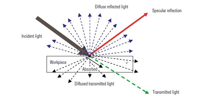
Using the incident light as 100%, the ratio of light specularly reflected is called specular reflectance, the ratio of other reflected light is called diffuse reflectance, and the sum of the two is called total reflectance.
There are three main types of lighting directions used with machine vision.
-
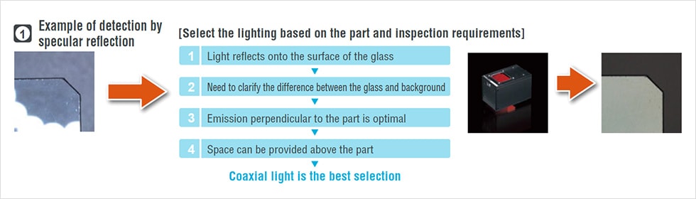
- Specular reflection type
- Lens receives light that specularly reflected off the target, which works effectively with parts with reflective properties, such as a glass substrate.
-
- Diffuse reflection type
- Lens receives uniformly distributed light while releasing the specularly reflected light. This type is effective for inspections done through transparent tapes in order to ignore reflective parts.
-
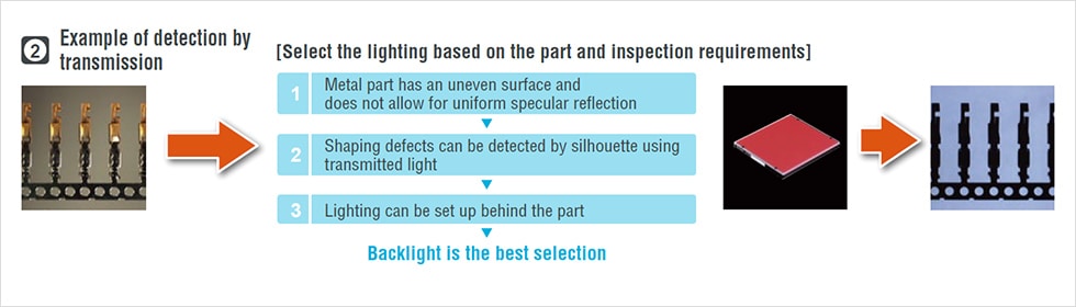
- Transmission type
- Light is emitted from behind the target to detect the silhouette with the transmitted light. This type is useful for parts that easily pass light, such as non-woven fabric.
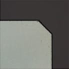
(1) Example of specular reflection type
Glass substrate flaw inspection
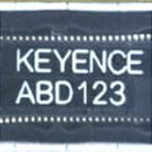
(2) Example of diffuse reflection type
Microchip print inspection over film
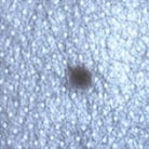
(3) Example of transmission type
Foreign particle detection in non-woven fabric
Point 1:
Determine the direction of the light based on the material/shape of the target and the inspection purpose. Select from three options: specular reflection, diffuse reflection, and backlighting.
Step 2: Determining the lighting type and shape
After determining the lighting direction, select the lighting type (model) based on the inspection requirements, background, and ambient environment. From the lighting options for each lighting direction, select the suitable lighting type as illustrated below.
| Typical lighting type for each lighting direction | |||
|---|---|---|---|
| Specular reflection | Coaxial light | Ring light | Bar light |
| Diffuse reflection | Low angle light | Ring light | Bar light |
| Transmission | Light source | Bar light | - |
Step 3: Determining the lighting color/wavelength
The final step is to decide the color of the lighting that works the best for the part and background. White is generally selected when using a color camera. However, when using a black-and-white camera, the following knowledge becomes more important.
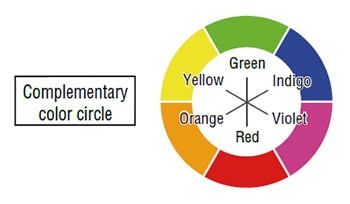
Complementary colors
Pairs of colors opposite each other on the complementary color circle are called complementary colors. When complementary color light is shined on a color, the color becomes close to black.
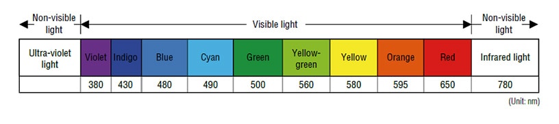
Wavelength
Light appears as a different color depending on the difference in wavelength. For example, light with longer wavelength (red) passes through films easily while light with shorter wavelength (blue) is more prone to diffusion with unevenness in the surface, such as scratches.
Point 2:
Instead of trying every light without due consideration, you can select the correct one efficiently by following the procedure below:
- Decide which type is appropriate: specular reflection, diffuse reflection, or backlighting.
- Decide on the shape (model) and size of the light.
- Decide on the color (wavelength) of the light.
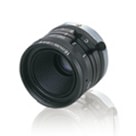
Step 4: How to calculate the focal distance and field of view
One of the lens specifications is focal distance. Typical lens sizes used in factory automation include 8 mm 0.31", 16 mm 0.63", 25 mm 0.98", and 50 mm 1.97". You can calculate the working distance (WD), which is the point at which the camera comes into focus, from the field of view (FOV) and focal distance necessary for the target to be captured.
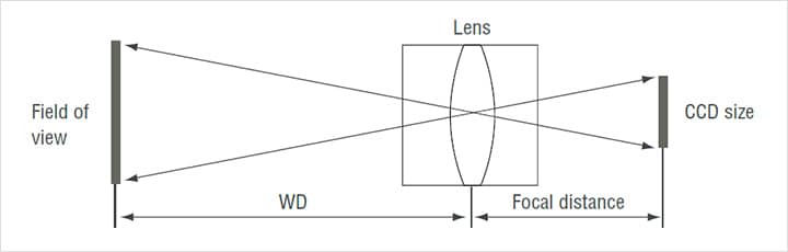
The WD and FOV values depend on the lens’ focal distance and image sensor size. For WDs greater than the minimum WD where a close-up ring is unnecessary, the WD can be estimated using the following proportion.
WD: Viewing angle = Focal distance: sensor size
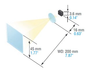
Example 1: When using lens with a focal distance of 16 mm
(0.63") and the image sensor size is 3.6 mm (0.14"),
WD should be 200 mm (7.87") in order to have a field
of view of 45 mm (1.77").
Step 5:
How to increase the depth-of-field (range of heights at which the lens remains in focus)
- Lens with shorter focal distance has a greater range of depth.
- As the distance to the target gets farther, the deeper the range of depth becomes.
→Note that the depth-of-field is smaller when using a close-up ring or macro lens. - The smaller the opening of the aperture, the deeper the range of depth is.
→It is easier to obtain focus using aperture zoom and bright light.
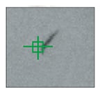
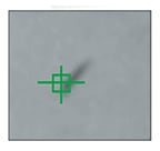
This example compares the image captures obtained with a smaller aperture and max. aperture when capturing a target that has a tape attached to indicate the height on a slope as shown in the figure below.
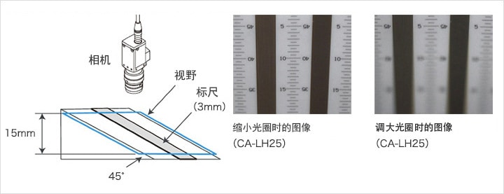
Step 6: Contrast ratio based on lens performance
The images on the right show the same target, captured using KEYENCE’s high-resolution lens CA-LH16 and standard lens CV-L16. The difference in the images derives from the differences in lens material and structure. Selecting a high-resolution lens depending on the application can provide images with higher contrast.
| Lens | CA-LH16/CV-L16 |
|---|---|
| Inspection target | Copying paper |
| Field of view | 60 mm 2.36" / Stain size: approx. 0.3 mm 0.01" |
Point 3:
Select a lens by following the procedure below:
- Decide the focal distance based on the image capturing size and possible installation distance.
- Estimate the necessary depth of field based on the shape of the target.
- Select whether to use a high-resolution lens or a standard lens based on the inspection accuracy.


![A Technical History of Image Processing Vol.1 [Camera]](/img/asset/AS_46814_L.jpg)
![The Latest Image Processing Applications [Transportation Industry]](/img/asset/AS_71759_L.jpg)

![The Latest Machine Vision Inspections [Food and Medical Industries]](/img/asset/AS_72814_L.jpg)