The Circuit Boards That Run Embedded Software
Many products, from familiar household appliances to automobiles, medical devices, and industrial machinery, contain “embedded devices.” These devices are small compared to the main body and may look like simple boxes.
However, there is always a PCB inside, on which embedded software runs continuously. The PCB is equipped with electronic components such as microcontrollers, memory, sensors, and communication ICs, each of which plays an important role.
When developing embedded software, it is necessary to consider the component configuration mounted on the PCB and the associated physical constraints.
- What is the “Microcontroller (MCU),” the Brain of Embedded Systems?
- What is “Memory,” the Microcontroller’s Workspace? | The Roles of ROM/RAM and Strict Memory Constraints
- What is a “Sensor,” the Interface Between Microcontrollers and the Real World? | Types and Key Points to Avoid Design Failures
- What is Embedded Communication? | Designing for Stability with Failure in Mind
- What is Embedded “Power Supply Design”? | Issues Misidentified as Software Bugs
- Understanding PCBs: Essential for Embedded Software Design
What is the “Microcontroller (MCU),” the Brain of Embedded Systems?
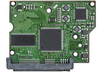
At the core of the PCB is the microcontroller (commonly called an MCU) or microprocessor (MPU). Comparable to the human brain, this part is a control center that executes programs, performs calculations and judgments, and issues instructions to surrounding components based on the results.
Functioning in Conjunction with Various Parts
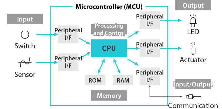
Both microcontrollers and microprocessors are equipped with a CPU (Central Processing Unit). This CPU executes programs, performs calculations, and makes decisions. Specifically, it receives information from sensors and, depending on the results, operates motors, lights up lamps, or performs communication. A microcontroller is usually equipped with I/O (called peripherals) for connecting these sensors and motors, allowing them to be connected and controlled on a single chip. On the other hand, microprocessors rely on I/O functions external to the chip, but they typically offer higher computational power than microcontrollers. Microprocessors are suitable for applications that do not use much I/O and specialize in computation, such as image processing.
However, the microcontroller itself cannot operate alone. A system that can be used as a product is only established when a stable power supply, a clock circuit that controls normal operation timing, a reset circuit that ensures startup when power is turned on, and debug terminals used for programming and troubleshooting are all in place. In embedded software development, it is necessary to take into account the characteristics of these peripheral circuits.
What is “Memory,” the Microcontroller’s Workspace? | The Roles of ROM/RAM and Strict Memory Constraints
Along with microcontrollers, memory is also important; in embedded devices, ROM (non-volatile) and RAM (volatile) are mainly used.
The Roles of ROM and RAM
Since ROM does not lose its contents even when the power is turned off, it serves as a place to store the program itself, initial setting values, log data, and so on. RAM is a work area for storing calculations in progress and temporary data, and its contents are lost when the power is turned off. RAM includes SRAM, which has a fast processing speed, and DRAM, which has a large capacity and is inexpensive. In embedded devices, SRAM is basically selected for reasons such as power efficiency and circuit simplicity. In embedded devices, these memories are used differently depending on the application.
When using a computer or smartphone, you are rarely aware of a lack of memory. However, because memory capacity is extremely limited in embedded devices, the approach of using as much as is available runs the risk of causing problems. In particular, RAM is easily consumed as the amount of processing increases, and if the design is incorrect, it can cause malfunctions such as sudden stops after operating for a long time. Therefore, the basic rule is to avoid dynamic memory allocation as much as possible.
Regarding memory, instead of thinking about using all that is available, it is necessary to think about how to avoid using it and secure adequate headroom.

What is a “Sensor,” the Interface Between Microcontrollers and the Real World? | Types and Key Points to Avoid Design Failures
Sensors are used to detect the state of the outside world. Sensors convert various physical quantities in the real world, such as temperature, acceleration, pressure, light, and sound, into electrical signals and transmit them to the microcontroller. Recently, various types of sensors, such as gyro sensors, geomagnetic sensors, humidity sensors, and gas sensors, have become smaller and more affordable and are now installed in a wide range of products.
Two Types of Sensors and Design Points
There are two types of sensors, digital and analog. For connections between digital sensors and microcontrollers, digital communication methods such as I2C (Inter-Integrated Circuit) and SPI (Serial Peripheral Interface) are used. In the case of analog sensors, an ADC (Analog-to-Digital Converter) is used to convert the analog signal into a digital signal that can be read by the CPU before it is fed to the CPU.
What is important in sensor design is setting the timing and frequency of detecting the outside world. Reading too frequently leads to an increase in processing load and power consumption, while conversely, if the interval is too long, necessary changes will be missed. For example, for a temperature sensor, reading about once every few seconds to a few minutes is basically sufficient, but for vibration detection, sampling in units of tens of milliseconds may be required in some cases.
Since there are cases where sensor values do not stabilize immediately after the power is turned on, warm-up time is also required. In addition, because errors may occur due to temperature changes, and there are subtle errors for each individual unit, mechanisms to handle errors, such as temperature compensation and calibration, are also incorporated into the software. These characteristics are described in the datasheets provided by sensor manufacturers, so it is necessary to read through them.
What is Embedded Communication? | Designing for Stability with Failure in Mind
Embedded devices basically operate in coordination with other devices and networks. Therefore, communication functions using communication ICs are essential. Communication methods include wireless communication such as Wi-Fi and Bluetooth, and inter-device communication such as Ethernet (wired LAN), RS232C, and RS485. Especially in IoT devices, wireless communication technologies that operate with low power consumption and do not require wiring are used.
Designing with the Assumption of Connection Failures
When considering communication, the prerequisite to keep in mind is that “connections may fail.” In communication, you must understand that issues such as errors due to noise, the status of the device at the other end, temporary disconnection, and radio interference will inevitably occur. Especially in wireless communication, which is easily affected by the surrounding environment and obstacles, measures are required to maintain stable communication.
Therefore, in the design of embedded software, retransmission and recovery methods in case of communication failure must always be included. The quality of embedded software is reflected in settings such as the limit on the number of retries when transmission fails and the timeout period when no reply is received from the communication partner. Designing with the assumption that communication will fail, rather than assuming only normal operation, creates products that continue to operate stably in the field.
What is Embedded “Power Supply Design”? | Issues Misidentified as Software Bugs
The power supply circuit supports all components on the PCB. It converts power supplied from batteries, AC adapters, or outlets into the required voltage using DC-DC converters or regulators, and supplies it to each component. In many embedded devices, the voltage values used internally and whether power is supplied as AC or DC differ from the power supplied externally. If this power supply circuit is unstable, malfunctions or sudden restarts may occur even if the software is written correctly.
Identifying Power-Related Issues is Crucial
What complicates the issue is that these power-related issues can outwardly appear to be software bugs. This makes isolating the cause difficult. For example, if a microcontroller malfunctions due to power supply noise, it may at first glance look like a logical error in the program. In embedded software development, keeping these issues in mind, careful design is required that also considers initialization procedures at power-on, operation during voltage drops, and overcurrent protection.
For battery-powered devices, precise power management is crucial. Consideration is required to extend battery life as much as possible, such as cutting power to unnecessary components and utilizing low-power modes.
Understanding PCBs: Essential for Embedded Software Design
PCBs used in embedded systems contain components, each with a clearly defined role. Embedded software is designed to control these components accurately and perform reliable processing within a specified time under limited resources. In control where real-time performance is required, task priority management and interrupt processing design are also important.
Approaching Software Design with an Understanding of Hardware
In embedded software development, “performance that continues to run reliably for a long time without stopping or running out of control” is emphasized over high functionality. To achieve this, an attitude of designing software while understanding the various hardware constraints is required. Co-design of hardware and software aims to optimize the entire system.
Once shipped as a product, subsequent modifications are difficult, and any defects could lead to accidents. To prevent such situations, accumulated know-how has been compiled into guidelines. Useful references include “ESCR (Coding Standards for Embedded Software Development)” published by IPA, and “MISRA-C,” a coding guideline for increasing the safety and reliability of the C language. In addition, “datasheets” and “hardware development guides” published by various manufacturers should also be referred to. These documents describe recommended circuit configurations, initialization procedures, troubleshooting methods, and more. Even for elements with very similar characteristics, the details of their control methods often differ from manufacturer to manufacturer.
To understand embedded software, it is necessary to understand the roles and constraints of the components on the PCB. All hardware characteristics, such as microcontroller usage, memory size and speed, sensor accuracy and response time, communication speed and reliability, and power capacity and voltage stability, affect software design. Understanding the balance and division of roles between hardware and software is the starting point for creating high-quality embedded devices. On top of that, a highly reliable system is completed through repeated verification and debugging using actual hardware.