Introduction to Device Driver Development
While using a HAL speeds up development, overhead may prevent real-time requirements from being met. Conversely, direct register manipulation is fast, but portability becomes an issue. Have you ever run into such obstacles in embedded driver implementation?
In this article, we will organize how to choose between abstraction libraries, low-level libraries, and standard interface specifications, as well as the key points of common API design to prevent changes to upper layers. We will cover four themes: layer design, register practices, initialization and data transfer methods, and library comparison.
The text is written using general terms, and any specific examples are treated as illustrations not intended to recommend particular products. The concepts presented here can be applied to microcontrollers (MCUs: microcontroller units, small computers designed to manage specific tasks within embedded systems) from any manufacturer.
- Roles and Layer Design of Embedded Device Drivers
- Basic Practices of Direct Register Control
- Peripheral Initialization and Selection of Data Transfer Methods
- Comparison of Abstraction Libraries and Low-Level Libraries and Portability Design
Roles and Layer Design of Embedded Device Drivers
An embedded device driver is software that mediates between the hardware and the application layer. If the abstraction level of the driver is too low, dependence on specific hardware increases, reducing portability. Conversely, if it is too high, there is a risk of performance degradation due to overhead. Determining the level of abstraction that meets product requirements is the first step to getting started.
Three-Layer Model That Bridges the Gap Between Hardware and the Application Layer
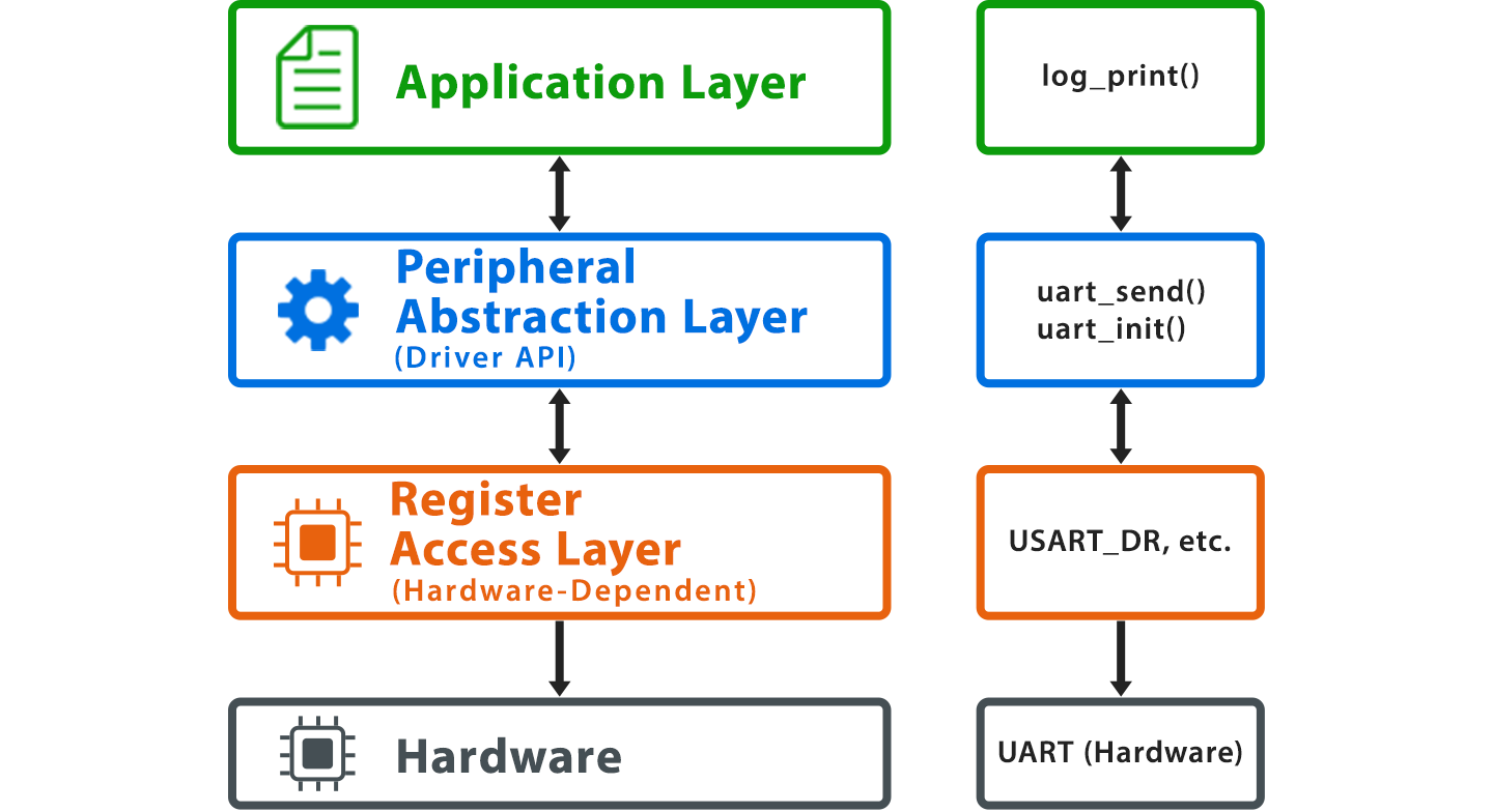
Generally, a three-layer structure consisting of a "register manipulation layer," "peripheral abstraction layer," and "application layer" is used. For UART, the hierarchy consists of the register layer for direct access to peripheral registers, the abstraction layer for uart_send(), and the application layer for log_print(). Register names vary depending on the microcontroller generation and vendor. For example, a common data register may be used for transmission and reception in one generation, while registers may be separated for transmission and reception in another generation.
How to Strike the Right Balance Between Abstraction and Layer Thickness
If only one type of peripheral is used, the layer can be thin. When porting between multiple microcontrollers, or when handling peripheral types (UART, I2C, SPI) with a unified API, a single abstraction layer is inserted. There are also many compromises where interrupt hot paths bypass abstraction, while abstract APIs are used for initialization and configuration changes.
Basic Practices of Direct Register Control
When operating memory-mapped I/O, it is important to note that register accesses may be omitted or reordered due to compiler optimization. To prevent the occurrence of non-reproducible bugs, it is necessary to use the volatile qualifier to prevent the adverse effects of optimization and use memory barriers to ensure execution order. It is important to master items such as volatile, ordering guarantees, and bitwise operations.
volatile, Memory Barriers, and Ordering Guarantees
By casting and referencing the register address with *(volatile uint32_t *), the compiler is forced to read from the register every time the value is needed. Depending on compiler optimization, memory attributes, and interrupt or exception boundaries, it is effective to explicitly specify the intended order using DSB (Data Synchronization Barrier), DMB (Data Memory Barrier), or ISB (Instruction Synchronization Barrier). For example, when an exception is expected after changing the Vector Table Offset Register (VTOR), the use of ISB in addition to DSB is advised. This is because old instruction fetches remaining in the pipeline can cause issues. Similar consideration is recommended after changing the priority of the interrupt controller, and on higher-end cores with L1 cache, this is combined with cache maintenance operations.
Bitwise Operations and Handling of Bit-field Structures
Individual bit manipulation of registers is basically a Read-Modify-Write such as reg |= (1U<<3) or reg &= ~(1U<<3). It is important to note that C-language bit-field structures are not recommended for register definitions because their memory layout is compiler-dependent. Writing with mask constants and shift amounts increases portability.
Utilization of Standard Interface Specification Definitions and Naming Conventions
Headers of software interface specifications standardized for microcontrollers provide access via structures like PERIPH->REG. While register definitions around the core are standardized by the specification, definitions for peripheral registers such as UART are generally included in device headers provided by each vendor. While device header definitions are easy to map to the vendor’s reference manual, note that peripheral names and register names are not always completely identical across vendors. Using bit definitions (such as PERIPH_REG_BIT) together can eliminate magic numbers (numerical values written directly in the source code). Note that version 6 of this specification is currently available, and each component has its own version. Functions for signal processing and neural networks are separated into independent packs. In version 6, support for the older generation RTOS API (v1) was discontinued, with support consolidated under the successor RTOS API (v2).

Peripheral Initialization and Selection of Data Transfer Methods
The difficulty of driver implementation lies in the initialization sequence and the selection of the transfer method rather than register manipulation. If the order of clocks, pins, and interrupts is incorrect, initialization will fail without any error output, and a mistake in selecting the transfer method directly affects CPU load and real-time performance.
Order of Clock Gating and Pin Configuration
If you write to a register before the peripheral clock is enabled, the value may not be reflected and the expected operation may not occur. Generally, the common sequence is to enable the peripheral clock in the clock control register, configure the GPIO Alternate Function Register, and then configure the peripheral control register.
Note also that the connection bus differs for each peripheral. Even for the same UART, the peripheral bus to which it is connected may differ depending on the product. Check the reference manual of the product you are using.
Criteria for choosing between polling, interrupts, and DMA
Selection is based on three factors: transfer volume, response requirements, and CPU load. Polling is standard for small, infrequent transfers; interrupts for moderately frequent transfers requiring real-time performance; and DMA (Direct Memory Access), which bypasses the CPU, for continuous large-volume transfers. Taking UART as an example, a common configuration is to implement debug output with polling, command reception with interrupts, and transmission of a certain amount of data with DMA.
Do’s and Don’ts for Interrupt Service Routines (ISRs)
As a rule, code inside an interrupt handler (ISR: Interrupt Service Routine) should be “short, minimal, and non-blocking.” Keep it to setting flags, pushing to ring buffers, or releasing semaphores, and delegate analysis and transmission to the main task. Avoid using printf, malloc, and long-duration polling inside the ISR.
Comparison of Abstraction Libraries and Low-Level Libraries and Portability Design
Vendor-provided HALs (Hardware Abstraction Layers) are convenient, but code size bloat and overhead are challenges. Low-level libraries (low-abstraction drivers close to registers) are lightweight and close to registers, and standard interface specifications have the strength of software standardization. Choosing among them according to product requirements is a practical approach.
Strengths and Weaknesses of Vendor HALs
Vendor-provided HAL transmission functions offer the convenience of initiating transmission with a single line. On the other hand, depending on the implementation, overhead can occur due to the management of peripheral control structures (handle structures) and callback dispatching. Low-level transmission functions are low-overhead wrapper functions that can be expected to be inlined, but going through the HAL adds validation of control structures, state transitions, and timeout management.
Deciding to Replace with Low-Level Libraries
Consider replacing with low-level libraries in areas with strict real-time requirements, mass production designs with tight ROM/RAM constraints, or when you want to avoid limitations imposed by HAL specifications. Replacing HAL transmission functions with low-level equivalent transmission functions that operate closer to the registers is one option. In some cases, you may choose to bring up the system with HAL during the prototyping stage and switch layers for mass production.
Cross-Vendor Positioning and Use Cases of Standard Interface Specifications
This specification is a set of independent, function-specific standards developed as a common standard for microcontrollers. Core access (interrupt controller, system timer, system control block) is provided by the core standard, signal processing by the signal processing library, and the RTOS API specification by the RTOS API (v2). A configuration where core functions are written using the core standard and peripherals are left to vendor libraries is widely adopted in practice.
Abstraction Patterns to Prevent Higher-Level Changes Using In-House Common APIs
Whether using HAL or LL, it is standard practice to isolate the application layer with an in-house API. With appropriately designed APIs, you can avoid making changes to the application layer even when replacing the internal implementation.
By following four approaches—the role of the driver layer, the practices of direct register control, the selection of initialization and transfer methods, and the combination of abstraction libraries, low-level libraries, and standard interface specifications—you can achieve implementations that are less susceptible to differences among vendors and peripherals.