Microcontroller Boards and Peripheral Boards
When developing embedded software, it is necessary to understand what kind of hardware the software runs on.
The foundation for this is the microcontroller board, and peripheral boards (expansion boards) are used to add various functions.
These two are basically used as a set and are utilized as the foundation for various products.
- Roles of Microcontroller Boards and Peripheral Boards
- Types of Microcontroller Boards
- Types and Roles of Peripheral Boards
- Points to Note in Embedded Software Development
- Summary
Roles of Microcontroller Boards and Peripheral Boards
A microcontroller board is a single board that integrates the circuits necessary to run a microcontroller (MCU: Micro Controller Unit). It is equipped with a power supply circuit, clock, programming/debugging circuit, I/O pins, LEDs, buttons, and more. When developing embedded software, instead of designing a board from scratch, prototypes are created by combining off-the-shelf microcontroller boards and peripheral boards. Using a microcontroller board that already has the necessary circuitry allows you to immediately write programs and proceed to operation checks, speeding up prototyping.
What Are the Additional Functions Added by Peripheral Boards?
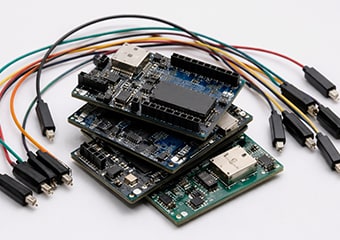
A peripheral board is a board used to add various functions to a microcontroller board. If the microcontroller board is the brain, the peripheral board plays the role of the five senses and limbs. For example, you can choose a board equipped with the necessary components according to your purpose—such as detecting surrounding conditions with a sensor, sending and receiving data with a communication board, or operating machinery with a motor driver—and connect it to the microcontroller board.
The combination of microcontroller boards and peripheral boards enables speedy software development. Previously, multiple processes were required, starting with board design, followed by component procurement, manufacturing, and mounting. However, by utilizing off-the-shelf microcontroller boards and peripheral boards, you can start operation checks as quickly as possible. This has made it possible to perform embedded development rapidly.
Types of Microcontroller Boards
Microcontroller boards can be classified into multiple types depending on the application and development stage. Here, we introduce four typical types.
1) General-Purpose Development Boards (Prototyping Boards)
These boards are widely used as standard options. They have many expansion terminals, and a wide variety of information and sample codes are available online. Representative products include Arduino Uno, ESP32 development boards, and Raspberry Pi Pico. The main applications are education-related, idea verification, and IoT prototyping.
2) Evaluation Boards (Evaluation Kits)
These boards are officially provided by semiconductor manufacturers that produce microcontrollers. They are designed to allow users to test all the performance and functions of the microcontrollers provided by each manufacturer to the maximum extent. The advantages are that they have extensive debugging functions and are equipped with dedicated development environments and libraries. Representative products include STM32 Nucleo and Renesas EK-RA Series. They are mainly suitable for industrial development and full-scale product verification.
3) Wireless SoC (System on Chip) Development Boards
These boards are equipped with wireless communication functions such as Wi-Fi and Bluetooth. You can immediately proceed with wireless communication development without worrying about antenna design or high-frequency circuit design. Representative products include ESP32-DevKitC and nRF52 DK. They are mainly suitable for developing IoT products and can simplify the implementation of wireless communication, which has high technical hurdles.
4) Single-Board Computers (SBCs)
These are high-performance boards that use Linux-based OSs, such as Raspberry Pi and NVIDIA Jetson. They are adopted when more advanced processing is required, as they enable image processing, AI inference, network processing, and more. Although they differ strictly from microcontroller boards because they use an OS, they share the common feature of exhibiting their functions in combination with peripheral boards.
| Board Types | Representative Product Examples | Main Applications/Advantages |
|---|---|---|
| General-Purpose Development Boards | Arduino Uno, ESP32, Raspberry Pi Pico | Idea verification, education, and abundant sample code |
| Evaluation Board | STM32 Nucleo, Renesas EK-RA | Full-scale product verification and extensive debugging functions |
| Wireless SoC Board | ESP32-DevKitC, nRF52 DK | IoT development and the peace of mind of a pre-designed antenna |
| SBC | Raspberry Pi, NVIDIA Jetson | Advanced image processing, AI, and utilization of Linux OS |

Types and Roles of Peripheral Boards
There are various types of peripheral boards depending on the purpose, and there are also multiple connection methods with microcontroller boards.
1) Expansion boards (shields/HATs)
These are types that are connected by stacking them on top of the microcontroller board, such as “shields” for Arduino and “HATs” for Raspberry Pi. Since almost no wiring is required, the advantage is that connection failures are less likely to occur.
2) Standardized modules (such as Click boards)
These are small boards that support standardized specifications, represented by mikroBUS and others. Since various functions can be swapped via plug-and-play without wiring peripheral devices, they are suitable for easily testing sensors, communication modules, etc.
3) Breakout boards
These are conversion boards that break out small and hard-to-handle ICs to easy-to-use terminals. They are used in combination with breadboards and jumper wires. They are items that facilitate prototyping and testing of sensors and ICs, making electronic work more efficient.
4) Classification by function
- Sensor boards measure temperature, humidity, acceleration, illuminance, distance, GPS, etc.
- Communication boards add communication functions such as Wi-Fi, Bluetooth, LoRa, LTE, CAN, RS-485, and Ethernet.
- Drive boards control components that handle large currents that cannot be directly supplied from the microcontroller, such as motors and relays.
- Display boards connect LCD and OLED displays to display information.
- Power supply boards perform voltage conversion, battery management, etc.
Points to Note in Embedded Software Development
While the combination of a microcontroller board and peripheral boards is very convenient, there are several points to note during development.
1) Voltage differences between the microcontroller and peripheral boards
Directly connecting a 5 V peripheral board to a 3.3 V microcontroller risks damaging the microcontroller. Use a level shifter (voltage converter) as necessary. Although most modern microcontrollers operate at 3.3 V, many older peripheral devices and industrial sensors operate at 5 V, so caution is required.
2) Ensuring power supply capacity
Wi-Fi modules and motors consume large amounts of current, even if only for a brief moment. If the power supply capacity is insufficient at that time, a “brownout” occurs, where the microcontroller resets due to a voltage drop. When designing, it is necessary to estimate the peak current and design the power supply with an adequate margin.
3) Managing pin conflicts
There are cases where multiple functions such as UART, I2C, SPI, and PWM are accidentally assigned to a single pin. To prevent conflicts, create a pin assignment table in advance during the early stages of development.
4) Confirming hardware requirements for communication
I2C and SPI will not operate unless the communication speed, address, and presence of pull-up resistors are correctly configured. In particular, I²C typically requires a pull-up resistor of around 4.7 kΩ. In addition, for most communications used in embedded systems, you can select a communication speed called the baud rate. When exchanging large amounts of data, a high baud rate is selected, but this makes it more susceptible to noise. Regarding the baud rate, it is necessary to select one that is necessary and sufficient based on the amount of data used. In order to communicate correctly, it is also necessary to select a common communication speed between the microcontroller and the sensor. Therefore, be sure to prepare hardware that can set a common communication speed.
5) Designing software structure
For board-dependent processing, it is recommended to separate it as a BSP (board support package) or HAL (hardware abstraction layer) rather than writing it directly into the application. This design is intended to facilitate the transition to mass-production boards in the future.
6) Gap between prototyping and mass production
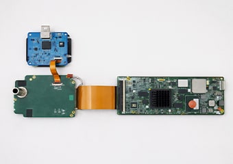
Just because it worked on a development board during the prototyping stage does not guarantee that it will work as is on a mass-produced product board. On production boards, problems that did not occur during the prototyping stage arise, such as noise introduced by wiring layout, inadequate heat dissipation design, and power supply quality. It is necessary to conduct rigorous evaluations that anticipate these troubles during the prototyping stage as much as possible.
Summary
A microcontroller board is a “foundation for efficient operation,” and peripheral boards are “tools for adding various functions.” Understanding and utilizing these two correctly can speed up development. When developing, a design philosophy that looks ahead to the transition to mass production—such as voltage, power supply, pin assignment, and noise—is essential. In particular, when transitioning from prototyping to mass production, problems that did not surface on the development board may occur. Therefore, conducting evaluations assuming the actual environment from an early stage and proceeding in a way that minimizes risks is the key to success.