GPIO Control and Switch Debouncing
Switch debouncing for GPIO inputs is an area that requires understanding the bounce characteristics of mechanical contacts and utilizing software and hardware. Implementation patterns include software debouncing using counter and shift-register methods, state design including long presses and repeated presses, and interrupt-driven debouncing with interrupt disabling and a two-stage timer. Combining these implementation patterns makes it easier to achieve reliable input operation without compromising button feel. This article organizes these into four themes: GPIO basics, software debouncing, state design, and interrupt-driven methods.
- GPIO Input Basics and How Chattering Occurs
- Software Debouncing Implementation Patterns
- State Design Including Long Presses and Repeated Presses
- Debouncing for Interrupt Edge Detection
GPIO Input Basics and How Chattering Occurs
Although GPIO input is a basic function of microcontrollers, it is an area with many troubleshooting issues in the field. Selecting pull-up resistors, understanding input thresholds, and understanding the physical phenomenon of chattering are prerequisites for stable button input design.
How to Determine Pull-Up/Pull-Down and Input Thresholds
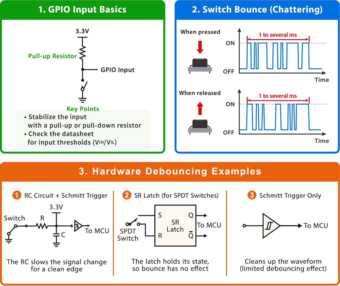
Since an open input pin has an unstable potential (floating), the potential is fixed with a pull-up or pull-down resistor. The value of the internal pull-up resistor varies by product family. As an example, a certain microcontroller specifies min 25 kΩ, typ 40 kΩ, and max 55 kΩ. (Since this value varies depending on the manufacturer and product family, be sure to check the datasheet of the product you are using.)
In noisy environments, selecting an external resistor of around 10 kΩ, which is lower than the internal pull-up (typically around 40 kΩ), improves noise immunity. The appropriate value varies depending on current consumption, wiring length, input leakage, rise time, etc., so it should be determined according to the requirements. When mixing 3.3 V and 5 V systems, it is necessary to check the input thresholds (VIH, VIL) in the microcontroller datasheet and take measures such as using a level shifter if necessary. Some microcontrollers from various manufacturers also support 5 V tolerant inputs.
Typical Values and Waveforms of Mechanical Contact Bounce
Contacts of tactile switches and relays vibrate mechanically, causing short repetitions of ON and OFF at the moment of pressing or releasing. In this article, this repetition of ON and OFF is referred to as chattering (contact bounce). The typical value is about 1 to several milliseconds.
Reports measuring multiple types of mechanical switches have confirmed cases where the bounce time exceeds 150 milliseconds. Inexpensive or aged switches may reach even longer bounce times. Looking at the waveform on an oscilloscope, a single press is observed as multiple pulse trains.
Hardware Debouncing Options (RC Circuit, SR Latch, Schmitt Trigger)
There are three main methods for hardware debouncing. The first method is to combine an RC integrator circuit with a Schmitt trigger IC. The SR (Set-Reset) latch method is used for double-throw (SPDT) switches and has been a recommended technique for many years.
A standalone Schmitt trigger is effective for waveform shaping (removing slow edges). However, it only suppresses analog fluctuations near the threshold, and the true bounce where the contact logically repeats ON and OFF remains. It is positioned as an auxiliary method rather than a dedicated debouncing technique.
In cases where high real-time performance is required or memory is constrained, implementing hardware debouncing is recommended. Note that for applications where software debouncing is sufficient, the implementation of hardware debouncing is often omitted.
Software Debouncing Implementation Patterns
While software debouncing can be implemented without additional components, it requires CPU resources and sampling design. Counter and shift-register methods are typical approaches, selected by considering the system’s purpose and the length of the confirmation time.
Periodic Sampling and Consecutive-Sample Counter Method
This method reads the GPIO state with a timer interrupt at a 10-millisecond (ms) cycle and confirms the state when the same value is detected in N consecutive samples. The implementation is simple and suitable for monitoring one to several single buttons. The elapsed time until confirmation can be estimated from the sampling cycle Ts and the number of matching samples N as Td = Ts × (N - 1). With a 10 ms cycle, 3 matching samples take 20 ms, and 4 matching samples take 30 ms.
Resource-Saving Monitoring of Multiple Inputs Using the Shift-Register Method
This method stores the sample value of each cycle into an 8-bit variable while shifting it to the left, and detects 0xFF (8 consecutive Highs) or 0x00 (8 consecutive Lows). Since it only requires 8 bits per input, it is suitable for monitoring a large number of input pins. This is a widely used classic technique, and the confirmation time can be adjusted by changing the number of shifts.
How to Determine the Sampling Cycle and Confirmation Time
The sampling cycle is set shorter than the chattering time, and the confirmation time is set longer than the chattering time. For a switch with a 1 to 5 ms bounce, one approach is to set a 5 ms cycle and 5 coincidences to achieve a confirmation time of 20 ms. Do not forget to estimate the execution time of the ISR (Interrupt Service Routine); designing so that the worst-case execution time falls within 30% of the sampling cycle is a safe level based on empirical guidelines.

State Design Including Long Presses and Repeated Presses
Debouncing that only detects presses and releases cannot handle operations such as long presses, double-clicks, and continuous presses. Managing this with a state machine allows you to implement these action detections and switch debouncing separately.
Four-State Model: IDLE, PRESS, HOLD, and RELEASE
It is managed with four states starting from IDLE (not pressed) and transitioning to PRESS (press confirmed), HOLD (press continuing), and RELEASE (release confirmed). By incorporating debounce confirmation into the transition conditions between each state, you can distinguish action types while preventing false detections.
Detecting Long Presses, Short Presses, and Double-Clicks
The elapsed time from PRESS to RELEASE is used to distinguish between a short press (less than 300 ms) and a long press (500 ms or more). The product’s UI specifications must explicitly define whether the intermediate range (300 to 500 ms) is classified as a short press or a long press, or treated as invalid. If there is another PRESS within a certain period of time (300 ms) after RELEASE, it is treated as a double-click.
Separation of Responsibilities Between Switch Debouncing and State Transitions
If the low-level module generates the debounce confirmation signal and the high-level module handles state transitions and action detection, testing and maintenance become easier. By replacing the debounce layer, it can also be applied to inputs other than physical buttons (such as touch sensors and remote controllers).
Debouncing for Interrupt Edge Detection
While designing button monitoring using GPIO interrupts offers excellent responsiveness, continuous interrupts caused by contact bounce may consume excessive CPU resources. One way to resolve this issue is a method that combines interrupts and timers.
The Problem of Repeated External Interrupts
The names and configurations of external interrupts vary depending on the microcontroller vendor; some have dedicated external interrupt controllers, while others handle IRQ pins via an interrupt controller. If an interrupt is configured on the falling edge, the ISR will be called for every bounce pulse. A single press can cause the ISR to be called a dozen times, potentially interfering with higher-priority processing. Debouncing implemented using interrupts alone—that is, a configuration without disabling interrupts or verification by a timer—is generally prone to malfunction.
A Standard Two-Stage Approach: Disabling Interrupts and Using a Timer
After receiving an external interrupt, the interrupt for the corresponding pin is disabled within the ISR, and a debounce timer is started. The timer value is adjusted based on the measured bounce time of the switch used, typically aiming for 10 to 50 ms. As a two-stage countermeasure, the GPIO is re-read in the timer’s ISR, and if confirmed, the main process is started, after which the interrupt is re-enabled. This suppresses continuous interrupts and reduces CPU load.
Compatibility with Power-Saving Modes
In battery-powered devices, there are situations where you want to put the microcontroller to sleep while waiting for a button press. Setting an external interrupt as a wakeup source allows the system to wake up upon a press, and after waking up, the debounce process is completed using the two-stage timer approach. The confirmation time is adjusted based on the oscillator stabilization time when waking up from sleep.
Contact bounce is an unavoidable physical phenomenon as long as mechanical contacts are used, and countermeasures are implemented by combining hardware and software. Standard methods include the counter and shift-register methods for software debouncing, the four-state model for long presses, and disabling interrupts combined with a two-stage timer for interrupt-driven operation. In this way, the pattern of “initialization, handler minimization, and delegation to higher-level tasks” used in GPIO interrupt processing is similarly applied to other peripheral functions such as I2C, SPI, and DMA.