Implementing Digital Filters
In digital filter design, it is necessary to consider limited computational resources and strict real-time constraints. This article clearly explains the background behind these requirements, key design considerations, and implementation precautions.

What is a Digital Filter?
A digital filter is a mechanism that filters an input signal to extract only the necessary frequency components. By using digital filters, such as averaging, to remove or reduce noise components introduced by sensors, analog circuits, or external disturbances, the influence of noise can be minimized.
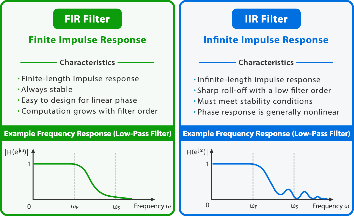
Digital filters are divided into two types: FIR (Finite Impulse Response) filters and IIR (Infinite Impulse Response) filters, which are used differently depending on their characteristics.
FIR Filters
An FIR filter is a digital filter whose impulse response becomes exactly zero after a finite amount of time. Because it uses only current and past input values, it is stable. A moving average, which is often used to smooth data, is a typical example of an FIR filter. Since the calculation formula is simpler than that of the IIR filter described later, it is also easy to implement. FIR filters with symmetric or anti-symmetric coefficients have linear phase characteristics, allowing signals to pass through while maintaining their waveforms.
IIR Filters
It is called IIR because it does not become strictly zero with a finite number of samples and has an infinite-length response. It is calculated using a combination of poles and zeros. It is characterized by the ability to operate with limited memory and computational resources because fewer coefficients are required. However, designing the desired filter can be difficult because the placement of roots (poles) where the denominator polynomial of the transfer function H(z) equals 0, roots (zeros) where the numerator polynomial equals 0, and phase distortion must all be considered. Depending on the position of the poles, the output may increase over time and diverge. It is also prone to instability depending on the parameters.
Precautions for Implementation
The following are points to keep in mind when implementing and coding digital filters.
Selecting Data Types
The difficulty of implementation varies depending on whether you choose fixed-point or floating-point. In the case of FIR filters, since it is easy to know the range of numerical fluctuations in advance, implementing them using fixed-point arithmetic is not very difficult.
Implementing IIR filters using fixed-point requires scaling design, which increases computational cost. Since avoiding overflow is also highly difficult, using floating-point is suitable if you want to simplify the implementation.
Numerical Stability
In principle, any order can be implemented, but implementing a high order as a single direct form is prone to numerical errors. From the perspective of numerical stability, it is recommended to decompose the transfer function into lower-order sections (first- or second-order sections) and implement them in cascade form (SOS: Second-Order Sections).
Coding should be done on the assumption that calculation errors will occur to some extent. Even if errors occur in internal calculations, FIR filters operate without diverging because they are stable. In IIR filters, rounding errors accumulate, making coefficient design and accuracy management essential. If phase control that is highly sensitive to deviations is required, it is better to consider implementation with an FIR filter.
Memory Usage
In FIR filters, the combination of a delay element and a multiplier is called a tap. The larger the number of taps, the more past data is retained, which increases the amount of data stored. As a result, the frequency of memory accesses increases, leading to a load on the entire system.
IIR can achieve amplitude characteristics equivalent to FIR with fewer coefficients than FIR, but it retains past output values in memory. In IIR, which feeds back output values to use in the next calculation, accurate management and initialization are required to handle cases where the returned value is abnormal.
Design Method
Development proceeds smoothly if you start designing in Python, where parameter adjustment is easy, and then port it to C. By using Python, which is available for free, and libraries such as SciPy and NumPy, it becomes easier to create filters with the desired characteristics. Libraries also provide many other necessary functions, such as pandas for converting data into tables and matplotlib for graphing filter characteristics.
While developing in Python, processing speed is rarely a concern during operation checks, but in reality, real-time processing is required. When optimizing in C, you adjust the number of multiplications and memory accesses.

Choosing Between FIR and IIR Filters
Phase linearity is important in scenarios where the shape of the waveform itself is emphasized. In such cases, FIR is suitable. If the phase is distorted, it can cause audio smearing in the audio field and blurred edges in image processing. By using a filter with linear phase characteristics, all frequency components are processed with the same delay time, allowing filtering while maintaining the waveform.
On the other hand, to process quickly with limited resources, a low-order filter with a sharp cutoff is required. In this case, IIR is optimal. Since the computational load increases as the filter order increases, it is often used in microcontrollers and other devices where the computational load needs to be kept low. In communication systems, this technology is indispensable for separating signals in adjacent frequency bands and communicating in a narrow bandwidth.