Maximum Material Condition (MMC)
The maximum material condition is used when designing two mating parts.
Taking a shaft designed to fit into a bore as an example, this specification ensures that the shaft actually fits into the bore under the maximum material condition (MMC), while also preventing excessively strict size tolerance from being applied in order to avoid cases where the shaft does not fit into the bore.
- What Is ?
- Handling Size Tolerances
- Expressing Maximum Material Condition Using a Dynamic Tolerance Diagram
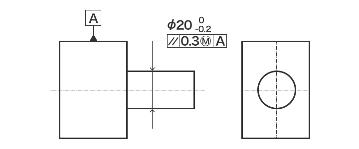
What Is ?
To apply the maximum material requirement to a dimension, you write after the size tolerance in the feature control frame. “M” stands for “maximum material condition" (MMC). This symbol indicates the application of maximum material requirement.
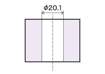
Handling Size Tolerances
Size tolerance is always followed when the maximum material condition is used. However, if a size tolerance is deviated from the maximum material size, the difference can be added to a geometric tolerance to make a virtual size.
-
Maximum material condition
-
Virtual condition
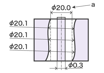
- a
- Virtual size
Expressing Maximum Material Condition Using a Dynamic Tolerance Diagram
The dynamic tolerance diagram is a tool that visually expresses the changes in the tolerance zone of size tolerance and geometric tolerance. By marking geometric tolerance on the vertical axis and size tolerance on the horizontal axis, the variations in both size tolerance and geometric tolerance can be presented at the same time. The application of the maximum material condition also clarifies the bonus tolerance that occurs when the geometric tolerance increases.
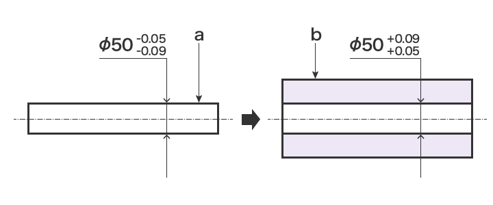
- a
- Shaft
- b
- Housing
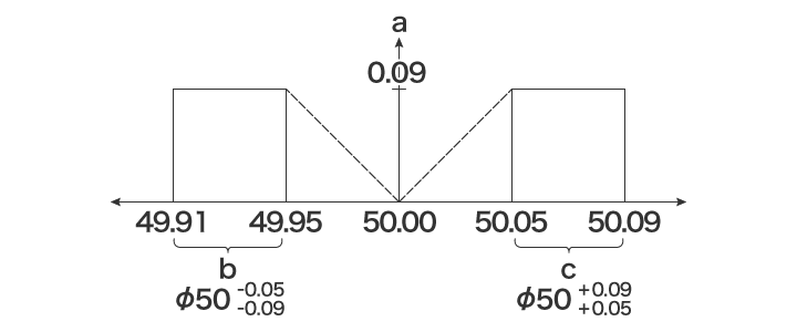
- a
- Straightness
- b
- Shaft size tolerance
- c
- Bore size tolerance

