Feature Control Frame
A geometric tolerance is specified in the feature control frame. The following elements are written in the feature control frame.
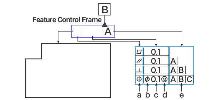
- a
- Geometrical characteristic symbol
- Write the type of geometric tolerance.
- b
- Diameter symbol (when needed)
- The geometric characteristics that need to be specified are as follows:
Area inside a circle on a two-dimensional plane: true position, concentricity
Area inside a cylinder in three-dimensional space: straightness, parallelism, perpendicularity, angularity, true position, coaxiality
Area inside a sphere in three-dimensional space: true position - c
- Geometric tolerance value
- Tolerance value. The unit is the millimeter (mm).
- d
- Material requirement, common tolerance zone, etc.
- Typical indications include (maximum material requirement), (least material requirement), and CZ (common [tolerance] zone). Others include and .
- e
- Priority datum
- The designer can specify as a datum the part that they want to prioritize as a reference. To specify multiple datums, write them in the order of priority (left to right).
Generally, designers determine the letter assigned to a datum in the order of priority—therefore, priority is generally described by alphabetical order.

