Marking Devices
This page introduces KEYENCE’s lineup of marking devices in addition to the supported networks and connection examples.
- Marking device lineup
- Connection example
- Network example
- Supported networks
- Typical connection example
Marking device lineup
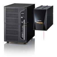
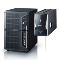
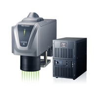
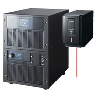
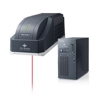
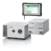
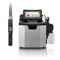
Marking devices
Connection example
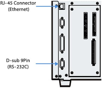
The various communication interfaces on the back of the marking device’s controller unit can be used for connections as needed.
Network example
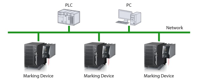
- A network-compatible unit or board is required for PLCs and PCs.
- A 1:1 connection is used for connections via RS-232C.
Supported networks
| Series | Field network | Other communication functions | ||
|---|---|---|---|---|
| EtherNet/IP® |
PROFINET |
Ethernet TCP/IP |
RS-232C RS-422A/485 |
|
| Laser Marker MD-X Series |
Field network
✓
|
✓
|
Other communication functions
✓
|
✓
RS-232C |
| Laser Marker MD-U Series |
Field network
✓
|
✓
|
Other communication functions
✓
|
✓
RS-232C |
| Laser Marker MD-T Series |
Field network
—
|
—
|
Other communication functions
✓
|
✓
RS-232C/RS-422A |
| Laser Marker MD-S Series |
Field network
—
|
—
|
Other communication functions
—
|
✓
RS-232C/RS-422A |
| Laser Marker MD-F Series |
Field network
✓
|
✓
|
Other communication functions
✓
|
✓
RS-232C |
| Laser Marker ML-Z Series |
Field network
✓
|
✓
|
Other communication functions
✓
|
✓
RS-232C |
| UV Laser Coder FP-1000 Series |
Field network
—
|
—
|
Other communication functions
✓
|
✓
RS-232C |
| Inkjet Printer MK-G Series |
Field network
—
|
—
|
Other communication functions
✓
|
✓
RS-232C |
Typical connection example
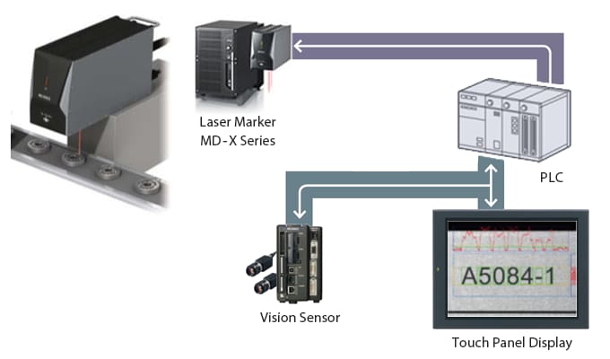
Connecting to a network makes it possible to collect and manage various information from marking devices. This allows for the construction of information systems for checking marking quality, predictive maintenance, changeovers, production management, and more.
The following example includes a network-connected marking device.
Batch management of setup changes in addition to character string marking control
Each product requires different marking information, so new lot numbers, expiration dates, and other information must be sent to the marking device as needed. Inspection systems can also be created by combining the marking device with a vision system that includes judgment functions.
