Examples
This page introduces welding control examples, including welding robot groove control and tracer control of weld lines.

- Example 1: Tracer control of weld lines (Torch position control)
- Example 2: Seam tracking control for laser brazing
- Example 3: Welding position measurement of ERW pipes
- Example 4: Height control of welding torch
- Column: Profile inspection of the electrode tip of a TIG welding robot
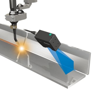
Example 1: Tracer control of weld lines (Torch position control)
Since laser welding is capable of fine working, its fusion area is limited. Consequently, it is essential to detect the weld line accurately and control the torch position through real-time feedback.
The LJ-X8000 Series High-speed 2D/3D Laser Scanner uses a laser line to detect the position or distance of the base material and the shape of the groove quickly and accurately to allow real-time torch position correction. This significantly reduces the time needed to adjust the welding robot torch position to achieve rapid and accurate automatic welding.

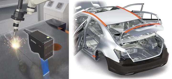
Example 2: Seam tracking control for laser brazing
Laser brazing is a process that uses the light energy of a laser to melt a wire-shaped filler material supplied between base materials to braze them. This can improve both the rigidity and processing time while maintaining the appearance of the base materials. Applications are increasing in the automotive and other industries as a next-generation joining technology to replace resistance spot welding which affects the appearance of base materials.
When laser brazing is applied to joining of roofs, side panels, and trunk lids of automobiles, seam tracking control is indispensable for accurate and rapid detection and tracer control of thin weld lines running along the complicated curved surfaces of car bodies.
The introduction of the LJ-X8000 Series High-speed 2D/3D Laser Scanner using slit laser light allows detection of the shape, position, distance, height and height difference of the seam where the filler wire will be inserted and laser will be aimed. This enables real-time robot control. These abilities are great advantages for improving the joining accuracy and processing time through the introduction of laser brazing.
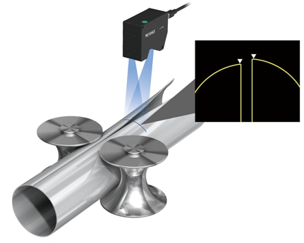
Example 3: Welding position measurement of ERW pipes
Electric resistance welding (ERW) pipes are characterized by smooth surfaces and high productivity. They are used in wide range of applications such as for energy field, mechanical structures and general piping. They are needed to ensure both high quality and safety, so highly reliable joint strength is essential.
ERW pipes are produced from a steel plate formed into a roll. The seam is welded with high-frequency induction welding. If the seam is misaligned, it cannot be welded properly.
The LJ-X8000 Series High-speed 2D/3D Laser Scanner can measure the height difference or gap in the material quickly and accurately by irradiating a large area with a wide laser beam. This allows checking the misalignment of the seam before it causes welding failure.
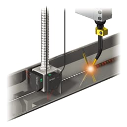
Example 4: Height control of welding torch
The height of the welding torch can be controlled in real time through the use of a laser displacement sensor during welding. The sensor quickly detects and feeds back the height change caused by the position, warpage, deformation, or height difference of the target. The data detected by the laser displacement sensor is fed back to the robot in real time for autonomous control to maintain the proper height of the torch at all times. This improves both the welding accuracy and processing time.
The LK-G5000 Series Ultra High-Speed/High-Accuracy Laser Displacement Sensor not only quickly detects the height of the weld line but also provides high-speed calculation and feedback of the measured data. This allows rapid and accurate torch height control, resulting in improved welding quality.
Even when multiple displacement sensors are used for the detection of the torch position, the LK-G5000 Series can control them with a single controller.

Column: Profile inspection of the tungsten electrode tip of a TIG welding robot
Robot TIG welding strikes an arc from a tungsten electrode to melt a filler rod and join workpieces. As the robot continues welding, the shape of the electrode may change. For example, the tip angle changes or bends, which can cause welding failure.
As a countermeasure, profile inspection using a 2D measurement system is added to the robot TIG welding process to provide quantified checking and maintenance of the electrode tip.
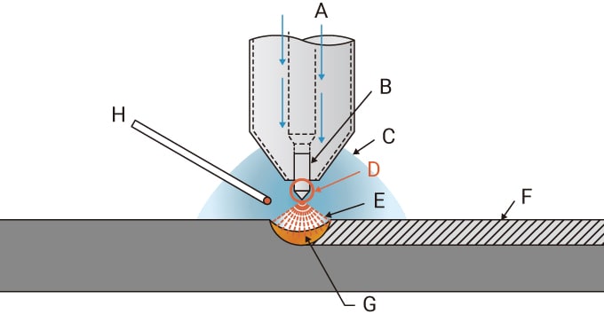
- Shielding gas
- Tungsten electrode
- Ar gas
- Tip of the tungsten electrode
- Arc
- Weld metal
- Weld pool
- Filler rod
[Introduction example] High-speed inspection of the profile of a tungsten electrode tip with a high-speed 2D optical micrometer
Install the TM-3000 Series High-speed 2D Optical Micrometer in the booth of a TIG welding robot. Considering the load applied to the electrode tip during the process, introduce a motion for profile inspection of the electrode tip using a high-speed 2D optical micrometer, once every 50 continuous welding actions.
The TM-3000 Series is capable of high-speed profile inspection. This prevents the occurrence of welding failures caused by changes in the electrode shape while minimizing the effect on processing time.
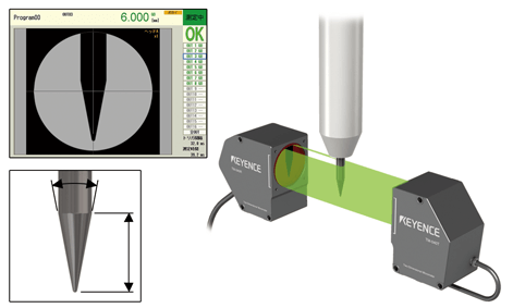
High-speed inspection of the electrode tip shape using the TM-3000 Series High-speed 2D Optical Micrometer


