Measurement Methods for Plural Connection
Methods for current measurement (4 to 20 mA) vary depending on how the 4 to 20 mA target output device is connected to one or more 4 to 20 mA input devices.
This section explains measurement methods when another 4 to 20 mA input device is connected (plural connection). There is a method using voltage input and another method using an instrument equipped with a 4 to 20 mA input. This section also introduces measurement principles and key points in selection for each of these methods.
Measurement method using voltage input
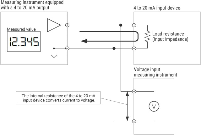
When the 4 to 20 mA target output device is connected to another 4 to 20 mA input device, measurement can be performed directly using an instrument that has a voltage input range. An important point is to measure the voltage after it has been converted from current through the load resistance of the 4 to 20 mA input circuit of the other device.
Wiring

Key points in selection
- Check the load resistance of the connected 4 to 20 mA input device. If the load resistance is 250 Ω, 4 to 20 mA can be measured as 1 to 5 V.
- For a small load resistance such as 1 Ω, the measurement accuracy and resolution may be reduced because the converted voltage also becomes small. In this case, use a 4 to 20 mA input device or shunt resistor described in the next section.
Measurement method using an instrument equipped with a 4 to 20 mA input
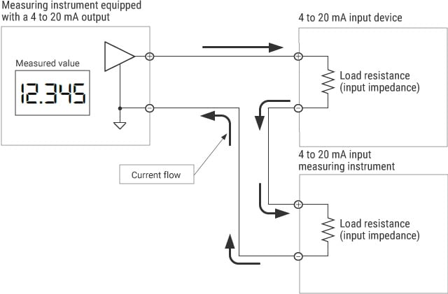
The user can measure two 4 to 20 mA input devices simultaneously by wiring them in series. This method enables accurate measurements even for a small load resistance, such as 1 Ω, of the other 4 to 20 mA input device.
Wiring

Key points in selection
- Satisfy the relationship of “maximum load resistance of the 4 to 20 mA output >= total load resistance of the two 4 to 20 mA inputs.” For example, if the maximum load resistance of the 4 to 20 mA output device is 260 Ω, two 4 to 20 mA input devices having a load resistance of 10 Ω and 250 Ω, respectively, can be connected in series.
- Because load resistances are connected in series, a potential difference occurs between the − terminals (GND terminals) of each input. Even if there is a potential difference, make sure that there are no problems in the whole circuit. For example, if the − terminal (GND terminal) of each input device is commonly connected to the − terminal (GND terminal) of the power supply, it is necessary to prepare another power supply to insulate them.
Measurement method using a shunt resistor to convert current to voltage
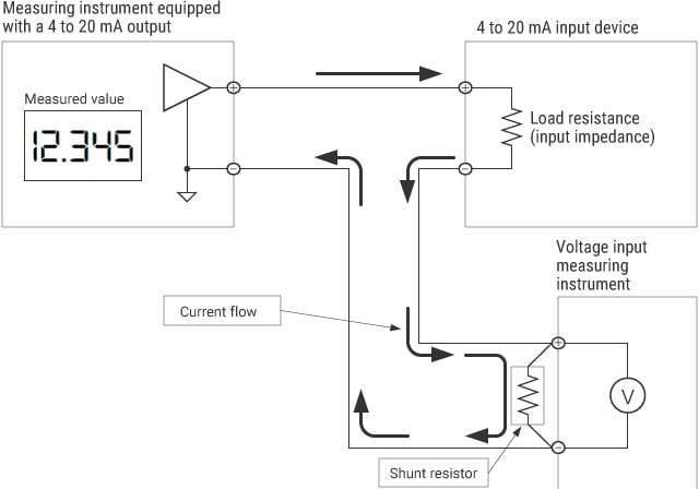
The user can perform measurement using an instrument that has a voltage input range by wiring the load resistance of the other 4 to 20 mA input device and a shunt resistor in series. This method enables accurate measurements even for a small load resistance, such as 1 Ω, of the other 4 to 20 mA input device.
Wiring

Key points in selection
- Satisfy the relationship of “maximum load resistance of the 4 to 20 mA output >= (load resistance of the 4 to 20 mA input + shunt resistor).”
For example, if the maximum load resistance of the 4 to 20 mA output device is 260 Ω, a 4 to 20 mA input device having a load resistance of 10 Ω and a 250 Ω shunt resistor can be connected in series. - Because load resistances are connected in series, a potential difference occurs between the − terminals (GND terminals) of each input. Even if there is a potential difference, make sure that there are no problems in the whole circuit.
- For details of how to select a shunt resistor, refer to “How to Select a Shunt Resistor.”


