Data Acquisition (DAQ)
Basics of Thermocouples
-
Tags:
- Data Acquisition , Temperature
This section introduces the basics of thermocouples, how to select them, and key points in using them.
What are Thermocouples?
Thermocouples are temperature sensors consisting of two different types of metallic conductors.
Thermocouples, mainly used for industrial applications, have the following features compared to other thermometers (such as mercury thermometers and thermistors).
- Quick response
- Capable of measuring a wide range of temperature between -200°C and +1700°C (-328°F and +3092°F)
- Capable of measuring the temperature of a specific point or in a small space
- Simple information processing and analysis thanks to temperature information detected as electrical signals (thermoelectromotive forces)
- Low price and easy availability
Principle of Thermocouples
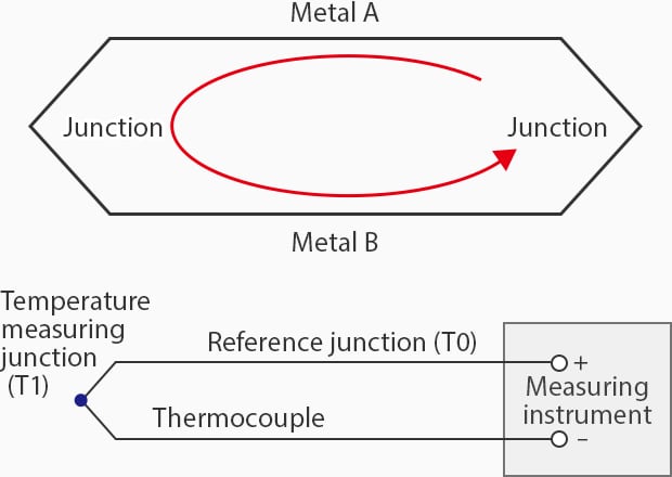
In 1821, a German scientist named Thomas Johann Seebeck discovered that when two different metals are connected and a temperature difference is applied to both junctions, voltage is generated between these metals, and current flows.
This phenomenon is named the “Seebeck effect” after its discoverer. This electric power that generates current in a circuit is called thermoelectromotive force and it has been confirmed that its polarity and magnitude are determined only by the materials of the two types of conductors and the temperature difference between both ends.
Using the Seebeck effect (explained above), a thermocouple generates a voltage according to the temperature difference T between the junction of the two types of metals (temperature measuring junction) T1 and the instrument-side junction (reference junction) T0.
Temperature measurement using a thermocouple measures this voltage with an instrument.
Measurement Methods Using an Instrument are Classified Into the Two Types Shown Below
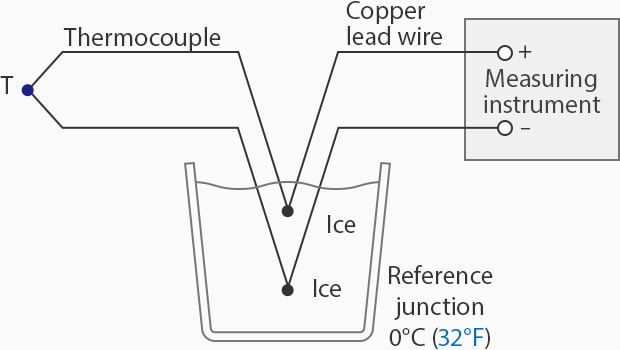
- Directly reading the temperature with the reference junction kept at 0°C (32°F) (cold junction compensation)
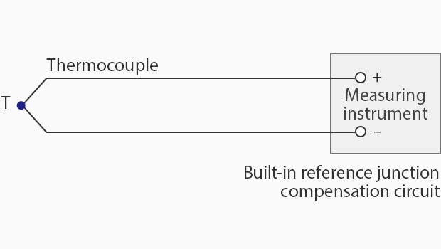
- Measuring the temperature of the reference junction (reference junction compensation) and adding it to the temperature difference ΔT
It is difficult to keep the cold junction at 0°C (32°F) during measurement. Instead, the temperature of the temperature measuring junction can be obtained by measuring the temperature around the terminal and adding to it a thermoelectromotive force with 0°C (32°F) as the reference. This is known as reference junction compensation.
Cold Junction Compensation
Reference Junction Compensation
How to Use a Thermocouple?
To use the thermocouple effectively for your application, you first have to consider the right type for your specific temperature range and environmental conditions—as discussed above, not all thermocouples are made equal.
Each thermocouple type is composed of different materials, which provides them with different temperature ranges and responses, so it's really important to consider your application. Once you've selected the appropriate thermocouple, you need to install it properly. This means that the thermal junction of the thermocouple should be in direct thermal contact with the surface or medium whose temperature we're measuring.
The thermocouple's wires should be connected to the appropriate measuring unit, such as a digital thermometer, a data logger, or a control system that can interpret the millivolt signal generated by the changes in temperature. Whatever the measuring unit might be, it's most likely equipped with a cold junction compensation, which is crucial for accurate temperature readings.
You, as the user or operator, must ensure that the instrument is properly calibrated, including the required compensation that matches the type of thermocouple used. These have to be properly configured to ensure correct temperature measurements and readings.
Adequately calibrated equipment and accurate readings enable you to monitor, record, and even control the temperature based on the needs of your specific application.
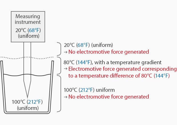
Where is the Sensor Section of a Thermocouple?
Take a thermocouple that is put in a glass of hot liquid.
The liquid is assumed to have a uniform temperature of 100°C (212°F) (no temperature gradient).
At this time, no thermoelectromotive force is generated in the thermocouple section in the liquid. A thermoelectromotive force is generated only where there is a temperature gradient.
Since the sensor section of the thermocouple is where a thermoelectromotive force is generated, this section with a temperature gradient is the sensor section.
What is the Output Measurement for a Thermocouple?
Thermocouples generate a small voltage that's directly related to the temperature difference between the thermocouple measurement juncture, also known as the hot juncture, and the reference (cold) juncture. This voltage is generated due to the Seebeck effect, which is caused when a circuit made of two dissimilar metals produces a voltage when there is a temperature difference between the two junctures.
The voltage generated by the thermocouple is usually in the microvolt to millivolt range and varies depending on the type of the thermocouple, the metals used in the junctions, and the temperature difference between the two spots. For example, a Type K thermocouple—made of chromel and alumel—generates approximately 41 microvolts per degree of Celsius on temperature difference.
The measurement instrument takes the generated voltage and converts it into a temperature reading by accounting for the reference junction, which is often done using a built-in junction sensor. The resulting voltage is then interpreted according to the type of thermocouple that is being used to measure temperature.

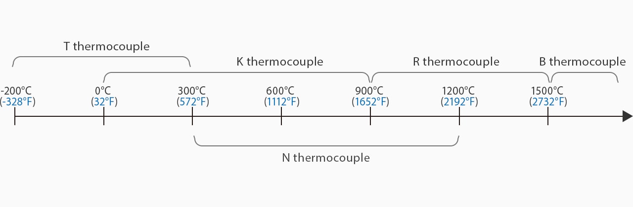
How to Select Thermocouples
Selection Based on the Measurement Temperature
The following eight types of thermocouples are available according to the combination of two types of metallic conductors.
| Type Symbol | Constituent Material | Measurement Range | |
|---|---|---|---|
| + Electrode | − Electrode | ||
|
Type Symbol
B
|
+ Electrode
Platinum‐rhodium alloy
containing 30% rhodium |
− Electrode
Platinum‐rhodium alloy
containing 6% rhodium |
Measurement Range
+600 to +1700°C (+1112 to +3092°F)
|
|
Type Symbol
R
|
+ Electrode
Platinum‐rhodium alloy
containing 13% rhodium |
− Electrode
Platinum
|
Measurement Range
0 to +1100°C (32 to +2012°F)
|
|
Type Symbol
S
|
+ Electrode
Platinum‐rhodium alloy
containing 10% rhodium |
− Electrode
Platinum
|
Measurement Range
+600 to +1600°C (+1112 to +2912°F)
|
|
Type Symbol
N
|
+ Electrode
Alloy mainly consists of nickel, chrome, and silicon
|
− Electrode
Alloy mainly consists of nickel and silicon
|
Measurement Range
-200 to +1200°C (-328 to +2192°F)
|
|
Type Symbol
K
|
+ Electrode
Alloy mainly consists of nickel and chrome
|
− Electrode
Alloy mainly consists of nickel and aluminum
|
Measurement Range
-200 to +1200°C (-328 to +2192°F)
|
|
Type Symbol
E
|
+ Electrode
Alloy mainly consists of nickel and chrome
|
− Electrode
Alloy mainly consists of copper and nickel
|
Measurement Range
-200 to +900°C (-328 to +1652°F)
|
|
Type Symbol
J
|
+ Electrode
Iron
|
− Electrode
Alloy mainly consists of copper and nickel
|
Measurement Range
-40 to +750°C (-40 to +1382°F)
|
|
Type Symbol
T
|
+ Electrode
Copper
|
− Electrode
Alloy mainly consists of copper and nickel
|
Measurement Range
-200 to +350°C (-328 to +662°F)
|
B, R, and S thermocouples are called noble metal thermocouples while N, K, E, J, and T thermocouples are called base metal thermocouples.
Noble metal thermocouples—which contain metals having a high melting point, such as platinum and rhodium—are generally used for measurement of temperatures of +1000°C (+1832°F) or higher, and base metal thermocouples are often used for measurement of temperatures below +1000°C (+1832°F).
The table below lists the characteristics of each type of thermocouple.
|
B Thermocouples
|
Has a higher melting point, mechanical strength, and long life due to a higher content of rhodium compared to other noble metal thermocouples. These thermocouples have an extremely low electromotive force and are incapable of measuring a low-temperature range. These thermocouples are selected to measure a further higher temperature range that cannot be measured using R or S thermocouples.
|
|---|---|
|
R and S Thermocouples
|
Selected when durability is required in a high-temperature range. Among all noble metal thermocouples, R thermocouples are the most commonly used.
|
|
N Thermocouples
|
Select these thermocouples when you want to measure a high-temperature range of +1000°C (+1832°F) or higher at a low cost.
|
|
K Thermocouples
|
Currently most widely used for industrial applications due to their lower price compared to noble metal thermocouples. First, consider using K thermocouples as they have good linearity in electromotive force and also offer high heat and corrosion resistance.
|
|
E Thermocouples
|
Feature an extremely high electromotive force per 1°C (1.8°F) and an excellent resolution. Select these thermocouples when you want to measure the temperature with particularly high precision.
|
|
J Thermocouples
|
Feature the second highest electromotive force per 1°C (1.8°F) (after E thermocouples) and an excellent resolution as well. Another feature is a lower price than that of E thermocouples.
|
|
T Thermocouples
|
Feature a good electromotive force characteristic in a low-temperature range (-200 to +300°C / -328 to 572°F). Select these thermocouples when you want to measure a low-temperature range with high precision.
|
Sample Selection of Thermocouples by Temperature
Selection Based on Environment-Friendliness and Responsiveness
The core fibers of a thermocouple are generally shielded from outside air to ensure resistance to oxidation and durability in corrosive environments.
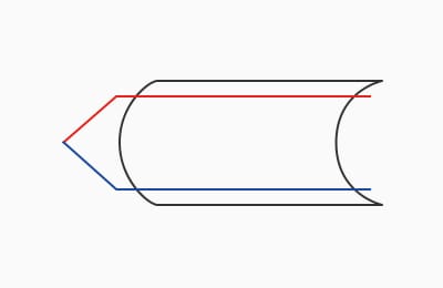
A thermocouple in which the area between its metallic sheath and a pair of thermocouple core fibers has been filled with powdery inorganic insulation is called a “sheath-type thermocouple.”
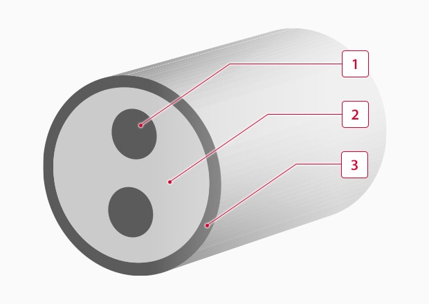
Cross-sectional view of a sheath-type thermocouple
Features of Sheath-Type Thermocouples
- Excellent flexural property and shock resistance thanks to high mechanical strength
- Excellent resistance to corrosion and pressure
-
1Thermocouple core fiber
-
2Inorganic insulator powder
-
3Metallic sheath
Due to the above features, the use of these thermocouples has been expanded gradually since they were put into practical use more than 10 years ago.
Temperature Measuring Junctions of Sheath-Type Thermocouples
Select the ideal junction type according to your application.
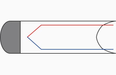
Grounded
A sheath-type thermocouple whose measuring junction has been created by welding its core fibers directly to the tip of the sheath. This type features quick responsiveness but cannot be used in noisy or hazardous locations because the core fibers are grounded to the sheath.
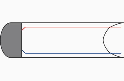
Non-Grounded
A sheath-type thermocouple whose measuring junction has been created with its core fibers insulated from the sheath. Although it has a lower responsiveness than the grounded type, this type can endure long-time use and can be used even in noisy or hazardous locations without being affected.
Exposed
A sheath-type thermocouple whose measuring junction has been created with its core fibers exposed from the sheath. This type has the highest responsiveness among the three types and follows even a slight temperature change. This type is used when quick responsiveness is required, such as during engine testing, but is disposed of after use due to its extremely low strength.

Key Points in Using Thermocouples
What are Compensation Lead Wires?
Compensation lead wires refer to conductors used to connect thermocouples and temperature-measuring instruments.
As they have an almost equivalent thermoelectromotive force characteristic to that of thermocouples in their operating temperature range (0°C to +60°C / 32°F to +140°F), they are mainly used to extend thermocouples.
Why Must Compensation Lead Wires be Used to Extend Thermocouples?
Let’s assume the following temperature gradient.
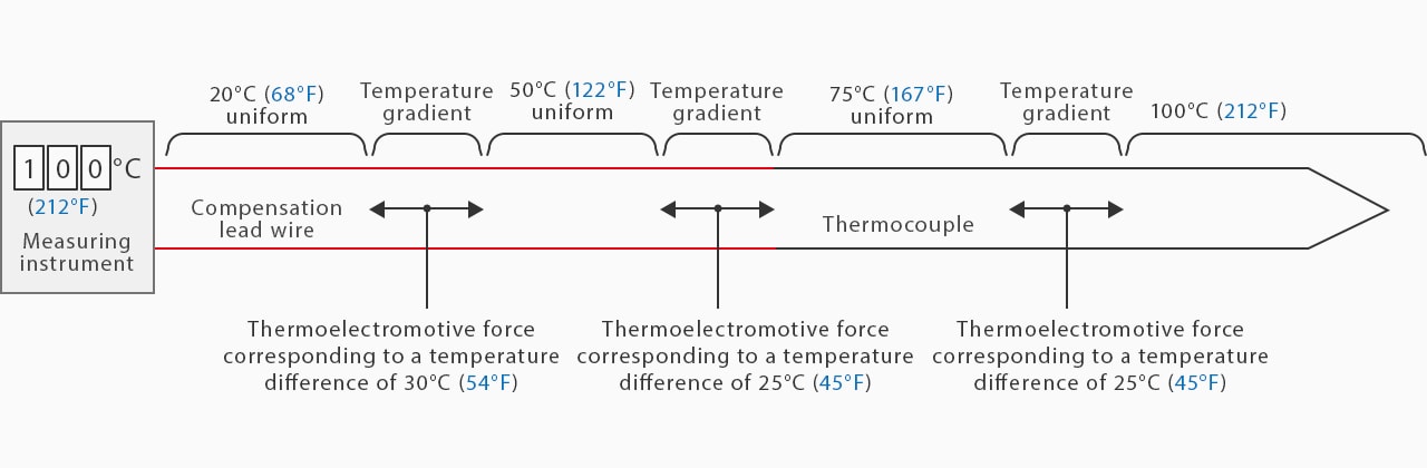
20°C (68°F) (reference junction compensation) + 30°C (54°F) + 25°C (45°F) + 25°C (45°F) = 100°C (212°F)
Because the temperature sensing section has a temperature gradient, a thermoelectromotive force corresponding to that temperature difference is also generated on the compensation lead wire. The instrument calculates the total of the generated thermoelectromotive forces and displays the results as the temperature.
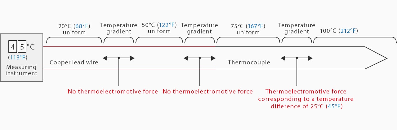
20°C (68°F) (reference junction compensation) + 0(0) + 0(0) + 25°C (45°F) = 45°C (113°F)
If a copper lead wire, instead of a compensation lead wire, is used as shown above, no thermoelectromotive force is generated even on a section with a temperature gradient. This issue generates an error in the results of the temperature measurement.
May Copper Lead Wires be Used If There is No Temperature Gradient?
In cases where there is no temperature gradient, no thermoelectromotive force is generated either. Therefore, copper lead wires may be used for the extension of a section having no temperature gradient where no thermoelectromotive force is generated.
Connection Between Thermocouples and Compensation Lead Wires
For a connection between a thermocouple and a compensation lead wire, a general terminal block may be used without any problems on the condition that there is no temperature gradient in the connecting section. However, it becomes impossible to perform an accurate measurement if a temperature difference occurs. In this case, use a dedicated connector that has a thermoelectromotive force characteristic that is equivalent to that of the relevant thermocouple.
Maximum Extension of Thermocouples
Thermocouples can be used even after being extended by 1 km or more. However, instruments generally have a specific “input signal resistance,” that is, the maximum resistance of input signals that can be wired. Note that accurate measurement becomes impossible if the total resistance value of the thermocouples exceeds this value.
Calibration of Thermocouples
Fixed Point Method and Comparison Method
Calibration of thermocouples refers to the operation that determines the relationship between the value indicated by the thermocouple being used and the true temperature. In general, calibration is performed once every half a year. Methods of calibration are largely classified into the fixed point method and the comparison method.
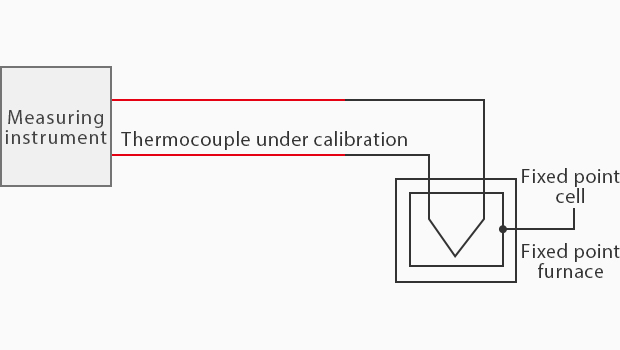
Fixed Point Method
The fixed point method is a method of calibration in which an accurate temperature value is given at the temperature fixed point.
As shown on the right, the temperature of the fixed point is measured to perform calibration.
As the temperature fixed point is in the phase equilibrium state of a substance, a specific temperature is always reproduced.
| Fixed Point | Temperature |
|---|---|
|
Fixed Point
Nitrogen Boiling Point
|
Temperature
-195.798°C (-320.436°F)
|
|
Fixed Point
Oxygen Boiling Point
|
Temperature
-182.954°C (-297.317°F)
|
|
Fixed Point
Freezing Point
|
Temperature
0°C (32°F)
|
|
Fixed Point
Water Boiling point
|
Temperature
99.974°C (211.953°F)
|
|
Fixed Point
Triple Point of Water
|
Temperature
0.01°C (32.018°F)
|
|
Fixed Point
Tin Freezing Point
|
Temperature
231.928°C (449.470°F)
|
|
Fixed Point
Zinc Freezing Point
|
Temperature
419.527°C (787.148°F)
|
|
Fixed Point
Aluminum Freezing Point
|
Temperature
660.323°C (1220.581°F)
|
|
Fixed Point
Silver Freezing Point
|
Temperature
961.78°C (1763.204°F)
|
|
Fixed Point
Gold Freezing Point
|
Temperature
1064.18°C (1947.524°F)
|
|
Fixed Point
Platinum Freezing Point
|
Temperature
1768°C (3214.4°F)
|
What is the Triple Point of Water (0.01°C) (32.018°F)?
The triple point of water is the temperature at which gas, liquid, and solid coexist and is generally realized by a glass cell called the triple-point cell of water.
This point is often used for the fixed point method as it gives the best accuracy of ±0.001°C (±0.0018°F).
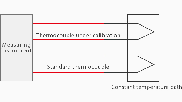
Comparison Method
The comparison method is a method of calibration in which the arbitrarily set temperature of a constant temperature bath is measured with a standard thermocouple to obtain an error against the thermocouple under calibration measured simultaneously.
Although the accuracy is lower than the fixed point method, this method allows for calibration at an optional temperature.
Service Life of Thermocouples
A thermocouple also has its own service life. Although it greatly varies depending on the operating temperature and atmosphere, noble metal thermocouples will last for approximately 2,000 hours, and base metal thermocouples will last for approximately 10,000 hours at a normal temperature or below in an oxidizing atmosphere. At the upper-temperature limit, the service life will be shortened significantly to approximately 50 to 250 hours. As a thermocouple is approaching the end of its service life, it does not show proper temperatures anymore and will eventually be disconnected. To ensure accurate measurement, be sure to regularly maintain and replace thermocouples.
Troubleshooting for Measurement Using Thermocouples

Sometimes, temperature measurement using thermocouples may not give you accurate values. A summary of typical problems found in measurement using thermocouples is given below.
The figure on the right shows a proper measurement using a thermocouple. The total thermoelectromotive force is 1.00 mV + 3.00 mV + 10.00 mV = 14.00 mV, resulting in a measured value of 100°C (212°F).
(Each thermoelectromotive force value is only for reference.)
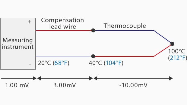
Wrong Polarity of Thermocouple and Compensation Lead Wire
Incorrect thermocouple and compensation lead wire polarity prevent accurate measurement.
The incorrect polarity results in a total thermoelectromotive force of −6.00 mV, thereby causing the instrument to show the wrong temperature.
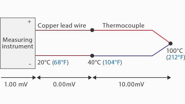
Instead of a Compensation Lead Wire, a Copper or Other Lead Wire is Used
In cases where there is a temperature gradient, the use of a lead wire made of copper or a similar material, instead of using a compensation lead wire, prevents accurate measurement.
The result of such a lead wire results in a total thermoelectromotive force of 11.00 mV, thereby causing the instrument to show the wrong temperature.
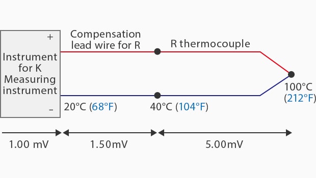
Different Types of Thermocouple and Compensation Lead Wires are Used
The use of a thermocouple and a compensation lead wire whose types are different from that of the instrument prevents accurate measurement.
Usage of these mismatched types results in a total thermoelectromotive force of 7.50 mV, thereby causing the instrument to show the wrong temperature.
KEYENCE’s products are designed for precise measurements and can help eliminate common problems such as incorrect polarity, mismatched types, and usage of incorrect materials.
Contact us today to learn more about our innovative solutions for your temperature-sensing needs.

![Temperature Measurement Basics [Thermocouples]](/img/asset/AS_118846_L.jpg)