CMM (Coordinate Measuring Machine)
CMM (Coordinate Measuring Machine)
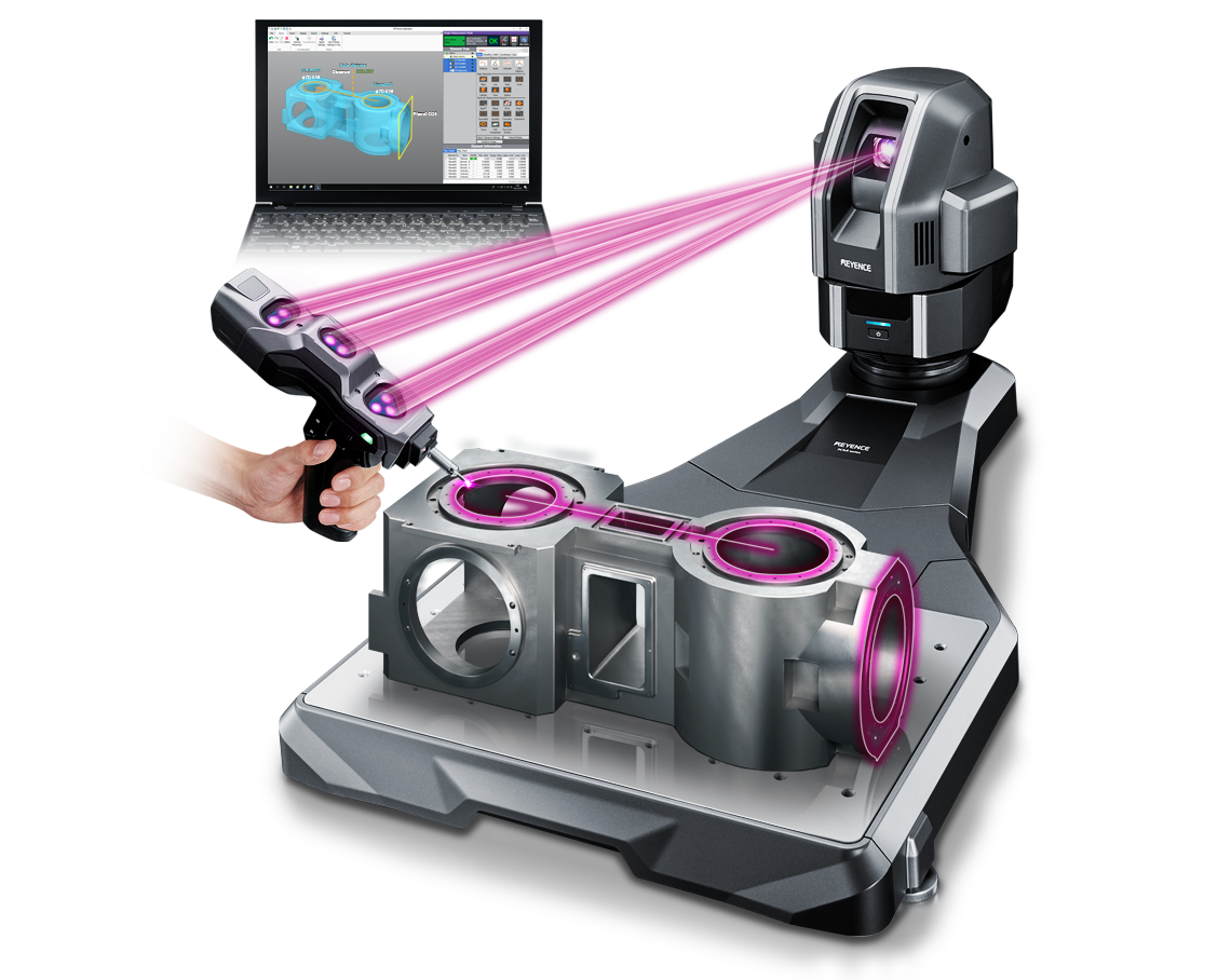
Our portable coordinate measuring machines allow anyone to easily measure 3D/GD&T features, compare to CAD, and automatically generate detailed inspection reports anywhere, including the shop floor. The handheld probe allows for the ease and full-range of motion of hand tools, while providing the capabilities and accuracy of a CMM. Along with no required CNC programming and no moving parts, our CMMs provide significant accessibility for companies with no previous CMM experience, or looking for complementary tool to reduce inspection bottlenecks.
Product Lineup
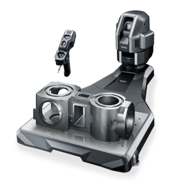
The XM Series is a handheld coordinate measuring machine (CMM) that lets anyone easily measure 3D/GD&T features. The system is portable and shop-floor ready, so measurements can be taken in any location. The unit also automatically records measurement data and creates detailed inspection reports. The images showcases our latest XM-5000 model which allows high-accuracy measurement for palm-sized parts to large applications.
Features
High-Accuracy 3D Measurement With a Handheld Probe
Targets can be approached from any angle, allowing for intuitive measurement. The measurement results displayed on the monitor are easy to understand and include images.
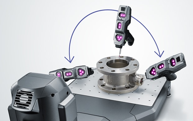
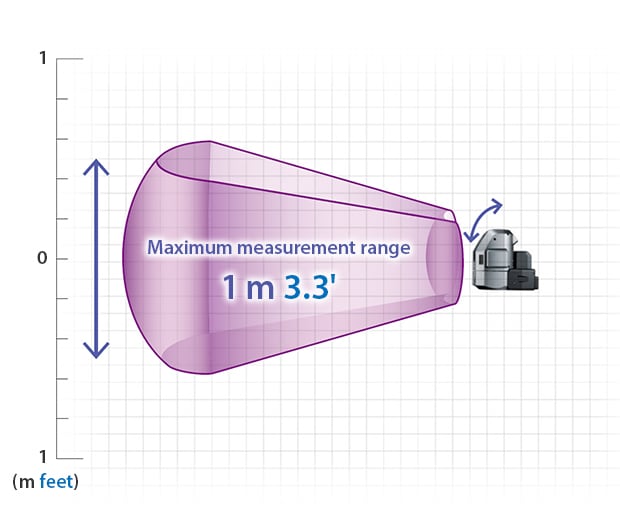
Large-Area Measurement With a Maximum Measurement Size of 2 m (6.6')
The measurement space is 66 times larger than that of conventional models. Everything from palm-sized parts to large parts can be measured.
Measurement Range in the Horizontal Direction
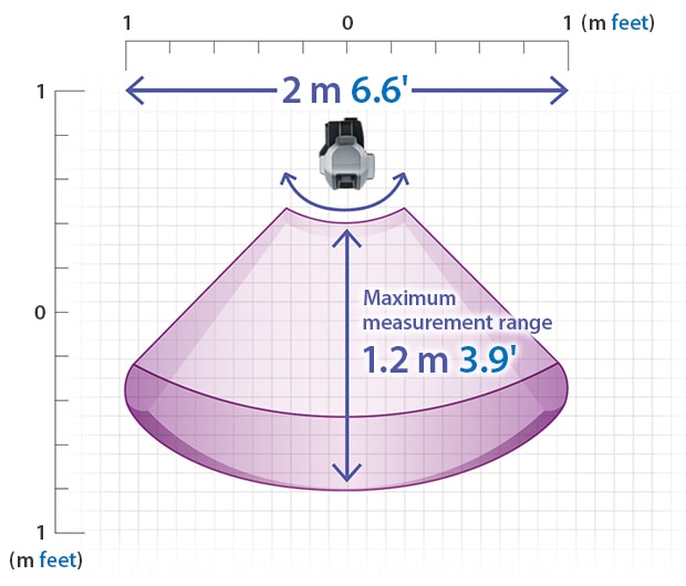
Measurement Range in the Vertical Direction
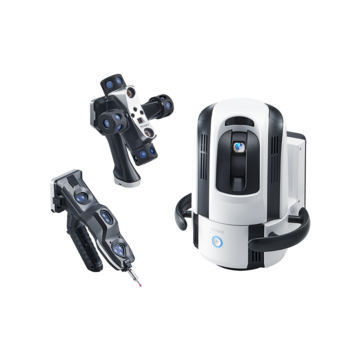
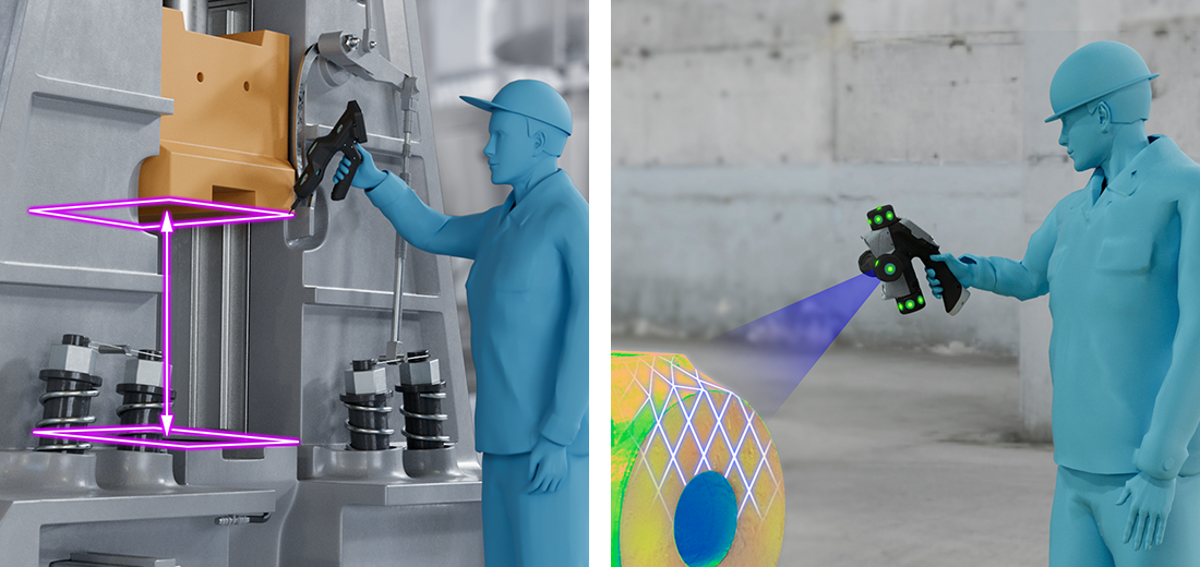
The Wide Area CMM WM Series of measuring instruments can easily measure the dimensions and shapes of products. Dimensions can be measured with the contact probe and shapes with the laser-scanning probe. The wireless probes eliminate routing limitations, allowing for easy measurement over a wide range. With no need for preprocessing such as spraying and sealing, scanning can be performed quickly and with high accuracy.
Features
Easy to Use for Anyone, Anywhere
Arm CMM / Hand Tools / Laser Tracker
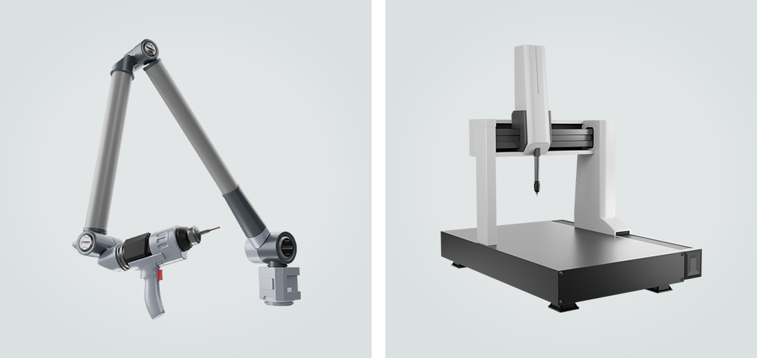
Difficult to Handle and Measure
- Limited measurement range and routing capabilties
- Restricted tool mobility
- Requires a highly-trained operator
WM-6000
Easy Inspection With Wireless Probes
- Wide measurement range with no routing limitations
- Flexibility with portable and wireless setup
- Immediately usable by anyone
Easy Single-Person Measurement of Large Targets
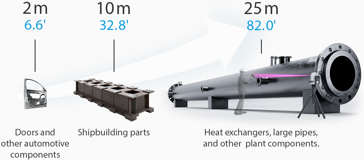
The wide measurement range of up to 25m (82ft) enables single-operator measurement of large applications across multiple industries.
A coordinate measuring machine (CMM) is a measuring device that measures the geometry of objects by establishing discrete points on a physical surface using a contact probe. The machine will specify the probe's position in terms of displacement from an origin point in a three-dimensional coordinate system (XYZ axes). A CMM can measure critical 3D dimensions with high-accuracy, record the measured data and obtain complex GD&T features. Non-contact models use other methods such as cameras and lasers.
Coordinate Measuring Machine (CMM) Parts
Typically, most CMMs are bridge or gantry-types as seen in the diagram. The spherical contact point attached to the tip of the probe is applied to the object on the stage, and the coordinate values in three dimensions (X, Y, Z) are specified and measured.
It is mainly used for three-dimensional measurement of dies such as automobile parts and various mechanical parts, three-dimensional objects such as prototypes, and measurement of differences from drawings.
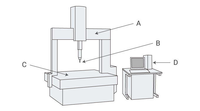
A: Moving bridge, B: Trigger probe, C: Stage, D: Controller
Benefits of Coordinate Measuring Machines (CMMs)
Coordinate measuring machines (CMMs) have three-dimensional measurement capabilities (X, Y, and Z directions), unlike hand tools such as micrometers, vernier calipers, or height/depth gauges, which are limited to measurement in only one direction at a time.
CMMs accurately track a probe tip in 3D space and create dimensional measurements through shape building via the points taken through contact with the measurement piece. An even greater number of points can be taken over a larger area on the part to map the surface and compare to CAD data for shape, form, and warpage inspection.
A powerful advantage of coordinate measuring machines (CMMs) is that they can measure items that are difficult to measure with other measuring machines to a high degree of accuracy.
Another feature that stems from the CNC nature of the measurement system, is the ability to measure the three-dimensional coordinates of a specific point (a hole, etc.) from the virtual origin with a hand tool such as a caliper or micrometer. Also, measurement using virtual points and virtual lines and geometrical tolerances are difficult with other measuring machines but can be measured with a 3D CMM machine.
Coordinate measuring machines (CMMs) are automated inspection tools. Skilled programmers create a measurement routine or program by measuring any required 3D or GD&T dimensions on a part.
Once the program is registered and an origin point is established through a coordinate system, parts can then be fixtured in place and operators can have the coordinate measuring machine run an automated measurement procedure. While there is a good amount of time invested in the program creation, the actual part inspection can be left to run automatically.
Place the measurement target in the metrology lab for at least 5 hours before measurement to allow the target to adjust to room temperature (generally 68°F). This will prevent measurement errors and discrepancies due to thermal expansion.
Perform measurements by directing the probe to your desired measurement location manually or with a control PC. The CMM will record the X,Y, Z coordinates of the probe location. As points are continued to be taken, the systems software will calculate specified dimensions such as diameters, lengths, angles and other critical dimensions.
Stylus Calibration (Probe Calibration)
Calibration on the stylus (probe tip) that comes into contact with the object must be performed in order to accurately begin measurement for two reasons. The first is to recognize the spherical center coordinates of the stylus. The second is to set the stylus sphere diameter. By setting the diameter, it is possible to calculate by offsetting the radius from the point actually touching (outside the sphere) to the sphere center coordinates.
For calibration, a sphere with a known sphericity, known as a reference sphere, is generally used.
Handling Precautions
Although some models can perform measurements on the order of 0.1 μm, correct usage and management are vital for measurement accuracy.
Verify that the moving parts move horizontally and vertically during use. Also, use a measurement standard or a similar object to check for indication errors.
In order to perform accurate measurements, allowing the temperature of the target to adjust to room temperature in the metrology lab is critical. Alternatively, the measurement parameters must be set to correct for any temperature difference.
For touch probes, it is important to ensure that the probe contacts the target at a constant speed during measurement.
Maintenance and Calibration
Regular CMMs require regular maintenance and inspection in order to carry out highly accurate measurements continuously. Especially in the case of a bridge-type CMM that are mechanically driven with sliding parts, it is necessary to regularly replace worn parts, lubricate, and clean the system for optimal performance.
Coordinate Measuring Machine (CMM) Operator Training
Careful handling of coordinate measuring machines generally requires advanced operator skills. Typically, CMM programmers are highly-trained metrology professionals.
CMM programmers are required not only for proper inspection, but a CMM may be damaged resulting in high repair costs if not used properly. For this reason, full-time inspectors are needed, and significant training is a pre-requisite for operation.
Coordinate Measuring Machine (CMM) Case Studies
Aerospace and Defense Industry
See case studies and white papers from aerospace and defense companies. The system's built-in SPC software automatically collects data and generates detailed inspection reports to help with AS9100 requirements. Example applications include precision machined components, castings, molded parts, and assemblies.
Machine shops
See case studies and white papers from small to mid-size machine shops or job shops. Whether requiring high-precision components that need the accuracy capabilities of a Coordinate measuring machine (CMM), or empowering inspectors and machinists to quickly inspect parts on the shop floor, the XM Series is the right tool for the job. Example applications include precision machined components.
Incoming inspection
See literature that reviews how to improve inspection efficiency and finish incoming inspection faster. Examples include Coordinate measuring machine (CMM) bottleneck prevention through quick part inspection, by anyone, anywhere in the facility.
Stylus / probe tip
Stylus of contact type CMM generally has a spherical diameter. Hard materials are often used at the probe tip - ruby and zirconia being the most common.
In addition to the spherical shape, a needle type with a sharp tip may be used.
Granite table
In order to realize highly accurate measurement, the surface of a coordinate measuring machine is often a surface plate made of stone. The stone surface plate has a very small change in shape over time and is not easily scratched, so it has the advantage that it can be used stably for a long time.
Fixtures
One of the more critical tools for using a coordinate measuring machine are fixtures for fixing a measurement target in place.
The reason measurement target is fixtured it does not move during CMM operation because part movement will lead to errors. It is common to use tools such as a fixture plates, clamps, and magnets.
Air compressors & dryers
Mechanically driven coordinate measuring machines require an air compressor with a dryer. This can be found is standard bridge or gantry-type CMMs.
Software
There are roughly two types of software for coordinate measuring machines.
The first is the software required to operate the machine. The second is a statistical process control (SPC) software that enables companies to view and monitor measurement data and statistics. These software packages come directly from the CMM manufacturer or from a third-party source.
Coordinate Measuring Machine (CMM) Measurement
CMMs generally have device coordinate system that is set in the object.
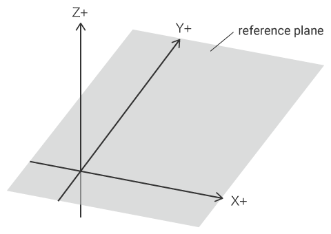
The device coordinate system is defined by the device, for example, the direction of the axis that moves in the lateral direction is the X axis, and the direction perpendicular to the stage surface is the Z axis. Therefore, depending on the orientation of the object to be measured, it may differ from the reference plane or reference line of the object itself. Since it is difficult and inaccurate to physically place this on the machine coordinates, the work coordinate system is set according to the reference plane or reference line of the object.
This way, aligning the orientation of the workpiece with the orientation of the reference coordinates is called alignment.
There are three pieces of information required to set the work coordinate system.
The first is the plane that is the reference plane, and the direction perpendicular to this plane is the Z axis.
The second line is the reference line, which is generally the X-axis and the vertical direction is the Y-axis. The straight line may be measured directly from the object, or it may be a straight line connecting two different points (such as two holes) with a virtual line.
The third point is the origin. This origin is the 0 point of each coordinate value of X, Y and Z. It is also possible to specify a specific point (for example, the center point of a specific hole) as the origin, or a virtual point (intersection point) where two straight lines intersect.
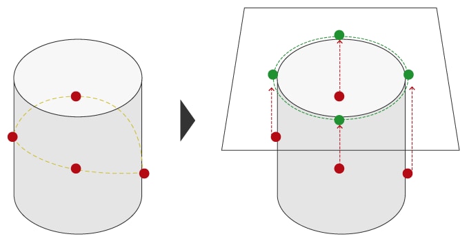
Generally, a user would select a measurement target called "element" such as a plane via a software menu and begin measurement. In the case of a contact type coordinate measuring machine, the stylus tip is brought into contact with the object to be measured, and the measurement point is taken. The element is measured by measuring the minimum number of measurement points specified for each element. If the number of measurement points is further increased, it is often calculated by the least squares method.
In addition to planes, measurement elements include lines, points, circles, cylinders, cones, and spheres.
Dimensions and 3D shapes are measured by calculating the distances and angles between measured elements.
Some elements have three-dimensional shapes such as cylinders and cones, but some elements do not have three-dimensional shapes such as lines and circles. These elements are generally projected on a plane (moved perpendicular to the plane direction) so that they can be measured correctly. The plane that is projected is called the reference plane or projection plane.
Coordinate measuring machines can also measure using virtual lines and points.
Various examples of virtual elements are used, such as intersections between straight lines, tolerances between planes, intersections between planes, and circles between cones and planes.
It can be said that measurement using these virtual elements, which is difficult to measure with hand tools such as calipers, is unique to 3D measurement.
Problems of Coordinate Measuring Machines (CMM)
To set and measure correctly, specialized knowledge and skills are required.
It is required to maintain an appropriate temperature in the measurement room and stabilize the temperature of the object.
Since it is necessary to calibrate every time various settings and probe angles are changed, it is not easy to support frequent product changes.
Since a measurement room is required, it is difficult to perform frequent measurements while processing the object.
The installation requires a large space and the construction of an environmentally-controlled quality lab which is extremely expensive.
Maintenance costs for the measurement environment and measuring equipment can be a burden.
Significant time is required to program the CMM for a few reasons. The required time run the part to the quality lab, acquiring the appropriate temperature for the part, fixturing, calibration for each probe tip and the time needed to complete the measurement.
KEYENCE’s XM Series is a new type of coordinate measuring machine that overcomes conventional CMM obstacles. It’s a portable, benchtop CMM that allows any operator easily measure 3D/GD&T features. The unit also doesn’t require a controlled environment and can be used on the shop floor. Learn more about this next-generation CMM!
Easy to use
As helpful as a conventional CMM machine is, a major drawback is the difficulty of operation. KEYENCE is committed to making the CMM machine experience easier by implementing an intuitive process. There are three simple steps when measuring: select, touch, and measure.
Both the WM Series and XM Series CMM programming have visual guidance for users and simple tutorials to combat any confusion. Once the measurement is imported into the software, there is additional guidance. KEYENCE’s CMM programming is built-in software that uses images, icons, and basic measurement practices.
Versatile
Conventional CMMs are either bulky handheld systems or gantry types that aren’t portable for bigger objects. KEYENCE’s XM Series and WM Series combat these two pain points with a wireless probe and a portable system that doesn't need a controlled environment.
The XM Series CMM machine comes with a benchtop measurement table for small parts, but the actual CMM tool can be attached to a tripod or mounting posts as well. Because of its portable nature, this same CMM tool can also be taken off the measurement table and easily used on large parts.
The WM Series is portable to help with measuring large parts and equipment. The tool can be moved and set up right at any required measurement location, and dimensional measurement of large products can be quickly completed by a single person in a short amount of time.
Wide-area
KEYENCE’s CMMs cover a wide area of measurement for a range of parts. The XM Series coordinate measuring machine has a maximum measurement distance of 1.2m from the camera and 1m vertical height. The full camera field of view enables a 2m end-to-end measurement range. This system achieves a wide measurement range with high accuracy measurement.
The WM Series ranges an even wider space: up to 7.5m vertically and 6m horizontally. Overall, the WM Series coordinate measuring machine detects a 15m length from the farthest right angle to the farthest left angle.
Related Products
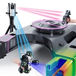
Introducing KEYENCE’s laser tracker with a dedicated wireless probe that eliminates movement restrictions when measuring large targets. Measurements can also be performed virtually anywhere with no need to take targets to a metrology lab, helping to reduce the time spent on measurement and improving operating rates. In addition, repeatability is extremely high—in the μm range—eliminating variations in measurement results for parts with complex shapes requiring high accuracy, including turbine blades.
The Resources of CMM
How to choose a CMM
Coordinate measuring machines (CMMs) are efficient and accurate measuring tools that outperform measuring alternatives like rulers, micrometers, and vernier calipers. These versatile machines measure the 3D dimensions, GD&T features, and compare to CAD in industries like healthcare, automobile, aerospace, and more.
However, not all CMMs are created equal– but that’s good news! CMMs have different measurement areas, software, and accuracy. Each of these factors should be taken into account when choosing the right CMM for your inspection or measurement needs.
With that said, if you are wondering how to choose a CMM, the following post will help.
Portable vs fixed CMMs and how to choose a CMM
Coordinate measuring machines (CMMs) are necessary tools for measurement and inspection in industries like aerospace, automobile, and medical devices. There are two types of CMMs, portable and fixed, and each has benefits depending on use.
When deciding between a portable or fixed CMM machine, understanding the key features that separate the two is imperative. In this blog, we’ll discuss what defines a CMM machine, the benefits of a fixed CMM machine, the benefits of a portable CMM machine, and the applications of each.
Laser tracker
KEYENCE America provides Laser Tracker; Our portable coordinate measuring machines allow anyone to easily measure 3D/GD&T features, compare to CAD, and automatically generate detailed inspection reports anywhere, including the shop floor.
Arm CMM
Discover KEYENCE's Arm CMM Solutions. Achieve precise measurements with portable and robotic arm-based CMM technology. Streamline your measurement process and accurately measure arm length.
How do laser trackers work?
Discover the power of laser tracking: Learn how laser trackers work and their role in precise measurements. Explore the capabilities of laser tracking systems and the role of operators.
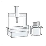
"Measurement Fundamentals" is an informative site offering knowledge related to dimensional measurements in manufacturing, including coordinate measuring machine (CMM) basics.
Frequently Asked Questions About Coordinate Measuring Machines (CMMs)
Coordinate measuring machines (CMMs) are intricate inspection tools with many moving parts, temperature and humidity sensitive components, and various fragile items. This makes the harsh production environments where there's a much higher potential for costly damage or nonoptimal measurement conditions leading to inaccuracies during the inspection. Quality labs are designed to be safe zones, environmentally regulated, and provides favorable conditions for proper inspection.
KEYENCE's XM Series handheld coordinate measuring machine is a portable, shop floor Coordinate measuring machine (CMM) designed to enable any user to easily and accurately measure 3D and GDT features, anywhere. Once the part is measured, the system automatically records the data and creates an inspection report. Our latest unit allows for CAD comparison and 3D CAD export. When compared to a traditional Coordinate measuring machine (CMM), companies see a significant reduction in inspection time and increased throughput through shop floor checks by anyone and helping to eliminate any Coordinate measuring machine (CMM) backlog.
![Perfect for High-Mix, Low-Volume Work Handheld Probe Coordinate Measuring Machine [Easy 3D and GD&T Measurement]](/img/asset/AS_116420_L.jpg)
The XM Series Handheld CMM is perfect for high-mix and low-volume work. See examples in this technical guide.
See common coordinate measuring machine application examples measured on the XM Series Handheld CMM. Application examples include: turned parts, machined parts, stampings, castings, and molded parts.
Using customer feedback, we compiled the 3 primary reasons they chose the XM Series as a complementary measurement system to their existing measuring equipment or CMMs.
An informative guide offering fundamental information related to dimensional measurements in manufacturing, including how to select the right tool for the job. Learn a wide array of inspection knowledge including optical comparator and coordinate measuring machine (CMM) basics.

