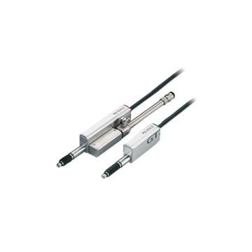
LVDT / Contact Displacement Sensors (Probes)
A durable and oil-resistant contact displacement sensor that can be used safely in environments exposed to water and oil. Along with a rich selection of heads, two detection methods are available, LVDT (linear variable differential transformer) and KEYENCE’s proprietarily developed Scale Shot System II.
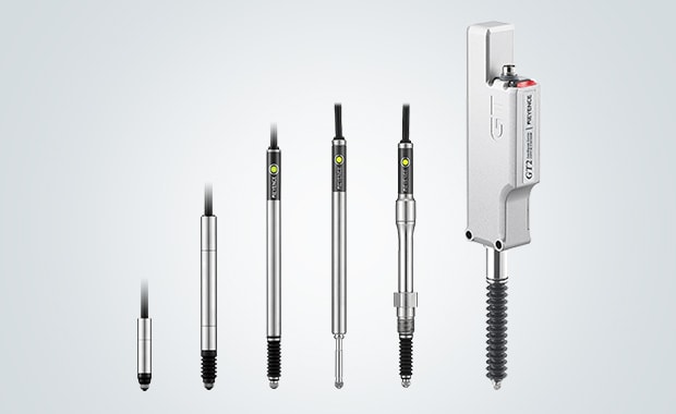
Product Lineup
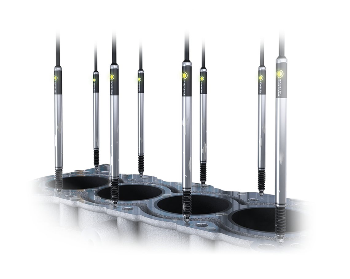
To increase longevity—a common challenge with contact-type displacement sensors—the structure of the main body has been fundamentally re-examined for the High-Accuracy Digital Contact Sensor GT2 Series. The structure, including the relay connector and cable, ensure stable measurement even in environments with splashing water or oil. In addition, the reduced weight of the spindle means minimal friction wear and significantly improved durability. A wide variety of sensor heads are available, including pencil type, air push-type, and low-stress type. The GT2 Series offers two types of detection methods: LVDT (linear variable differential transformer) and Scale Shot System II. This allows use across various applications. The varied lineup of communication units enables communication with PCs and PLCs from various manufacturers.
The General Purpose Digital Contact Sensor GT Series is a contact type sensor designed for ease of use and reliability. It can be installed easily in existing facilities, allowing for quick startup of the production line after installation. It also has an easy-to-see display and a self-diagnostic function for checking for conditions such as a trapped spindle or cable disconnection. There are two types of mounting for the amplifier: DIN type for rail mounting and panel type for panel mounting. Selecting the correct type for the installation environment is effective for simplified wiring. Various functions are included to complete the setting with minimum steps. The sensor can be used immediately after installation. The easy-to-see indicators clearly show judgment results and errors during measurement.
An LVDT (linear variable differential transformer) is a device that detects mechanical linear movement as displacement and converts it to electrical signals. Contact displacement sensors based on this method read changes in the shape of the target by converting it into electrical signals.
An LVDT type contact displacement sensor has a core at its center and coils around the core. A contact is attached to the tip of the core to make up a spindle. The spindle is pushed against the target with a spring mechanism. By using this spring force, the spindle can slide up and down according to the change in the shape of the target. The coil of an LVDT type contact displacement sensor generates a magnetic field when a current flows through it. When the core inside the coil moves, the impedance of the coil changes according to the movement, resulting in changes in the output signal level. The movement of the core shows changes in the shape of the target. Consequently, the displacement can be measured based on the detection of the change in the output signal level.
LVDT Mechanism
LVDT is an acronym for Linear Variable Differential Transformer, which is a kind of electromechanical transducer. An electromechanical transducer is an electronic device or element that converts one form of energy into a signal. The LVDT converts the linear movement of an object to which it is coupled mechanically into a corresponding electrical signal.
The internal structure of LVDT consists of a pair of secondary windings, a primary winding centered between the secondary windings, and a core placed in the cylindrical bore formed by the primary and secondary windings. These components are sealed with a heat-resistant material into a cylindrical shape and the whole structure is wrapped in a high-permeability magnetic shield for protection against moisture.
The primary winding is called the core wire. When the core wire (L3) is energized by alternating current, magnetic flux is induced and an induced voltage is generated in the secondary windings. If the core in the cylindrical bore formed by the primary and secondary windings is located midway between the secondary windings L1 and L2, their respective induced voltages (V1 and V2) will be equal. This means the differential voltage output is zero. If the core is moved closer to one of the secondary windings L1 or L2, the magnetic flux where the core is closer increases and a differential voltage output is generated.
The LVDT can convert linear displacement (position) from a mechanical reference (zero) into an electrical signal by using a feature of the electromechanical transducers, which outputs differential voltage that changes according to the core location. This electrical signal includes both phase (direction) and amplitude (distance) information.
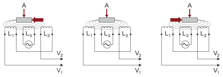
A: Core
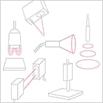
LVDT Application Examples
Since the moving parts of an LVDT have no contact with the transformer, it can operate without any built-in electronic circuits. This advantage means that LVDTs are widely used in applications that require long service life and high reliability in harsh environments. For example, manufacturing sites with demanding environments, the aerospace industry, and displacement sensors applications are all areas where LVDTs are used.
Unmanned autonomous vehicles (UAV):
UAVs control left/right rotation and backward/forward and up/down movements with actuators. Since they offer high accuracy and high reliability with light weights, LVDTs are often used for actuators in UAVs that are used in places inaccessible to humans, such as disaster sites and outer space.
Aircraft and spacecraft:
LVDTs are used for position monitoring in flight controls and engines, front wheel steering, and pilot controls. As they provide infinite resolution for linear position with an environmentally robust design, they are expected to be ideal for use in next-generation aircrafts.
Servo valves:
With the unique features such as high spool positioning responsiveness that allows for opening variations from halfway to fully open, stability that lets fluid maintain smooth movement even over extended periods of use, and high resolution, servo valves controlled with LVDTs are highly rated for their reliability and accuracy by mechanical and hydraulic/pneumatic system designers.
Benefits of LVDT / Contact Displacement Sensors (Probes)
Contact displacement sensors/LVDT are characterized by a compact sensor head and the ability to prevent tracking errors and unknown origin position. Although previous models had problems of errors caused by changes in temperature or by sensor head–amplifier combination, these design challenges have been solved in recent models.
Using a high-density coil can reduce the size of the sensor head. It is also possible to design the relay amplifier to include a circuit that offers optimized control of key components such as the coil, core, and transmission/reception circuits. This allows individualized tuning according to the status of each component and also enables correction for changes in temperature. These functions along with the LVDT principle allow measurement without tracking errors or unknown origin position. With conventional transformer methods, accuracy was affected by phase shifting of the analog waveform due to variations caused by amplifier and sensor head matching or changes in temperature. These disadvantages have been solved by contact displacement sensors/LVDT used in recent years.
They have an enclosure rating that offers high resistance to harsh environments. Every section is completely sealed so that the sensor can be used around splashing water or dust. This ensures accurate measurement even in harsh environments around manufacturing equipment.
In general, contact displacement sensors/LVDT comply with enclosure rating standards for water resistance, including the relay connectors and cables. This allows the sensor head to be installed almost anywhere, even in environments with splashing water. The cases are cast in one piece for a seamless and completely sealed construction, providing high durability. To ensure use in harsh environments for long durations, the sensor heads are sealed with gaskets resistant to degradation over time instead of adhesives. For the connectors, cables with high water resistance are used. Such a structure ensures accurate measurement for a long time even in environments with splashing water or dust.
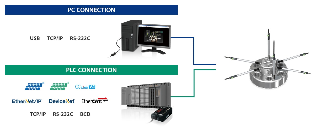
Contact displacement sensors/LVDT support major field networks and can be connected to PCs and PLCs. This is useful for setting multiple sensors collectively or collecting measurement results from multiple sensors.
Contact displacement sensors/LVDT can be connected to major networks including EtherNet/IP®, DeviceNet®, CC-Link, and EtherCAT® so communication can be established with PLCs and PCs from various manufacturers. They also can satisfy the need for value recording required for traceability or IoT. Moreover, the data of up to 15 connected units can be transmitted simultaneously. Settings can be changed from a touch panel, PC, or PLC, which can greatly reduce the setup time. The simplified wiring requires just a power supply cable and communication cable from the main unit. The amplifier wiring can also be simplified to greatly reduce wiring work.
LVDT / Contact Displacement Sensors (Probes) Case Studies
Gear assembly accuracy check and clearance measurement
Gears require high assembly accuracy because they need to receive strong forces and rotate at high speed. The clearances (gaps) between gears and surrounding components should also be strictly managed. Inspection after assembly is essential. There are many components around gears at high density, so measuring all clearances simultaneously requires installing sensors with a similar density. Since various oils and chemicals are used in the assembly process, the sensors to be installed must have enough resistance against the adherence of splashing oils and chemicals.
Contact displacement sensors/LVDT can measure the assembly accuracy of gears and the clearances around them with high accuracy on the order of micrometers. Thanks to their slim, pencil type case, multiple units can be installed within tight spaces. They also provide excellent resistance including the connectors and cables. There is no worry about corrosion or breakdown even in environments with splashing water or oil. The use of rigid components in sliding sections significantly reduces maintenance costs and replacement work.
Measurement of PCB warpage and height of mounted components
Sometimes the components mounted on PCBs are elevated due to PCB warpage or the components themselves are warped. In addition to defective mounting, the warpage of PCBs and components occurs due to degradation over time. Since these conditions may cause contact failure, it is necessary to measure the PCB warpage and the height of mounted components.
Contact displacement sensors/LVDT can be used for measurement of chip mounting height, confirmation of capacitor mounting orientation, and measurement of PCB flatness. Low-stress type models can measure with less load. The measuring force of 0.1 N reduces the load applied to products. This enables low-cost and high-accuracy measurement with no influence from surface conditions.
Measurement in tight spaces
When targets and small parts are positioned in close proximity, the mounting space is insufficient for other types of sensors. This creates a difficult application and requires extra effort such as dividing the measurement into multiple processes. If the measurement is still impossible, the inspection process must be revised.
On the other hand, the compact design of contact displacement sensors/LVDT allows multiple sensor heads to be installed in close proximity. They can also measure inflexible positions, such as a sensor head installed inside a cylindrical part to measure the inner diameter. Measuring multiple points simultaneously allows data collection all at once. This improves the accuracy of measurement data analysis.
Nine varieties of sensors are described based on the operating principle, structure, characteristics, and variations. This site provides basic information necessary for the selection of optimum sensors. You can learn about sensors starting from the basics.
Frequently Asked Questions About LVDT / Contact Displacement Sensors (Probes)
In general, contact sensors are said to have low reliability because they malfunction frequently due to wear or damage in the sliding section. For measurements at high frequency or that require many sliding actions, durability becomes particularly important.
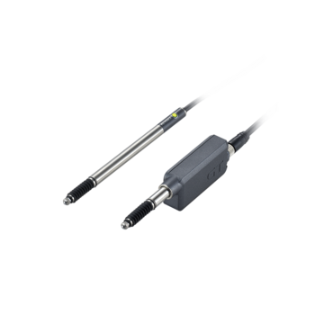
The GT2 Series uses high-strength linear ball bearings in its spindle. This has achieved a long service life of 200 million cycles. Also, using a fully stainless-steel construction for the spindle structure (shaft and bearings) reduces the weight. This helps to minimize wear due to sliding inside the spindle and dramatically improves durability. The cable between the relay connector and amplifier unit uses a flexible free-cut robot cable that resists continuous bending. Installation is possible even in environments where equipment is driven continuously.
Splashing of oil for suppressing friction or temperature rise due to friction is inevitable at the sites of cutting or polishing processes. For most sensors, oil not only prevents proper measurement but also causes malfunctions.
The GT2 Series complies with IP67G/NEMA Type 13 for its relay connector as well as sensor head. The sensor cable is made of polyurethane, a material with excellent oil resistance, to reduce cable corrosion. The sensor head body is cast in one piece for seamless construction. The completely sealed construction reduces the risk of the intrusion of water or oil.
Contact sensors using the LVDT (linear variable differential transformer) method have disadvantages such as accuracy decreasing near the edge of the spindle, and the magnetic field is applied evenly around the center but the balance becomes poor at the areas closer to the edge because the system is coil-based. On the other hand, those using the scale (pulse count) method have the disadvantage that when the spindle moves abruptly due to vibration or other reasons, the response of the photoelectric sensor may be delayed, resulting in tracking errors.
Scale Shot System II of the GT2 Series is a detection method that overcomes the disadvantages of these two methods. It locates the spindle using a CMOS sensor for high-speed scanning of the absolute value glass scale incorporating slits of complex patterns that vary depending on the position. This allows the sensor to detect position information as well as to obtain the absolute position. Consequently, it does not require zero-point adjustment or produce tracking errors. Moreover, the scale method ensures high accuracy over the entire measuring range.

This guide introduces how to measure thickness, height, runout, and stroke distance using the GT2 Series. It describes tips for problem solving and application examples in an easy-to-understand manner. This application guide is best suited to those who want to know what types of applications can be done.


This is an application guide summarizing actual examples of improved measurements in the automotive industry. It contains easy-to-understand descriptions with illustrations about advantages and features of the measurements enabled by the wide variety of sensor heads in the GT2 Series, such as assembly of engines, transmissions, batteries, ECUs, and inverters.
