CMM (Coordinate Measuring Machine)
Reverse Engineering
Key Takeaways
- Modern reverse engineering leverages CAD 3D software and CMMs to streamline product redesign, replacing traditional 2D trial-and-error methods.
- CAD files like DXF, STP, IGES, and STL serve specific purposes, ranging from 2D vector scaling to 3D printing and complex surface modeling.
- Integrating CMMs with CAD software enables real-time comparison between prototypes and original models via color-coded deviation maps.
- Efficient reverse engineering workflows involve scanning parts, generating CAD data, prototyping, and using CMMs to verify dimensional accuracy.
Reverse engineering has existed since the days of the first inventions. It’s a way to make an already-made product cheaper, more advanced, or update its design or function. It’s also used to reproduce another manufacturer’s product after detailed examination of its construction and composition.
Before the technology of today existed, reverse engineering used to be based off of 2D designs with lots of trial and error. But now, the integration of CAD 3D software streamlines the reverse engineering process with 3D designs, printing, and modeling. No longer do engineers have to figure out how to transition a 2D design into a 3D product.
With the use of CAD 3D software also comes reverse engineering tools like KEYENCE’s coordinate measurement machines (CMM). These CMMs work with CAD data files to collect dimensional and GD&T data more efficiently. Keep reading to learn more about the integration between CAD files and CMMs as reverse engineering tools.
How Can I Use CAD Files?
Using CAD files is helpful for creating an easy transition from a design to a model because the design is in 3D. CAD 3D software files store 3D wireframes, blueprints, and designs while also being collaborative across engineers and reverse engineering tools. Uploading CAD files into your reverse engineering tools allows for a comparison of your product or prototype directly to the original model.
Types of CAD Files
There are many different types of CAD files, a few KEYENCE works with are .DXF, .STP, .IGES, and .STL CAD files. Each one can be used for reverse engineering, but certain specialties make engineers use one file over another.
DXF File
DXF file is short for Drawing Exchange Format or Drawing Interchange Format.
DXF file is a vector file for 2D CAD, meaning that it uses mathematical formulas to alter the model sizing and design. Because of the mathematical integration, using this file allows for sizing up or down without distortions. The .DXF file is known for its ease of collaboration. Engineers share .DXF files across CAD programs and access an open format at all times.
STP File
STP file—also known as STEP, ISO 13030, P21-file, and STEP physical file—stands for Standard for the Exchange of Product Data. This file is a standardized format used for 3D models and designs. It’s also a vector file, and it's best used for 3D modeling and printing because of the ability to save a detailed and complete 3D body.
IGES File
IGES file is an older type of CAD file that stands for Initial Graphics Exchange Specification. It’s also a vector file, and it’s best for sending information between CAD applications and storing technical drawings like wireframes, circuit diagrams, and models.
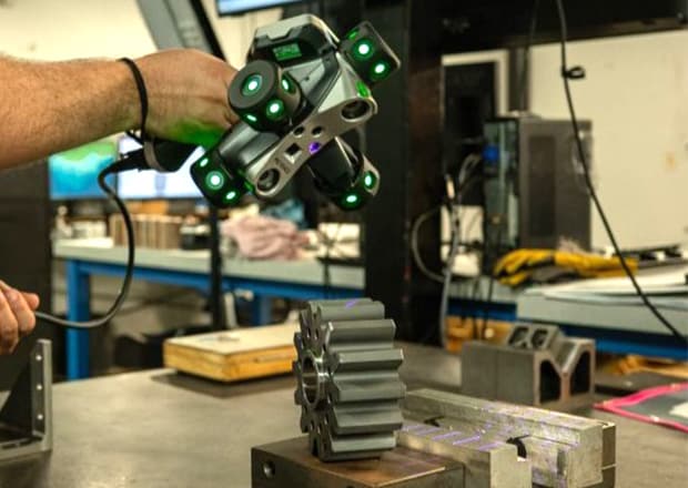
Handheld 3D Scanners, like the WM-6000 are able to scan a part and create an STL file in just a few minutes.
STL File
STL files, short for Standard Triangle Language, are a tessellated triangle surface file format , meaning the raw surface geometry of the 3D object is made by creating a "mesh" of interlocking triangles. They're often created when utilizing a 3D scanner, like the KEYENCE WM-6000 and are a great file to utilize for basic 3D printing of prototypes.
How to Use Reverse Engineering Tools with CAD 3D Software
KEYENCE’s CMMs are metrology tools that assist with the reverse engineering process by integrating CAD 3D software.
First, use the CMM to gather dimensions and GD&T features of the product that you are reverse engineering.
Then, use the data collected to build a model in one of the .DXF, .STP, .IGES, and .STL CAD files.
After creating your design, make a prototype. If you’re looking for an efficient method to move back and forth through the modeling and designing process, consider utilizing a 3D printer.
Once you have your prototype, bring the CMM over and touch the probe to the prototype. The CMM has a camera on the probe tip that overlays the 3D CAD image. In seconds, the CMM collects dimensions and GD&T data, and then the reverse engineering software will produce a CAD comparison color map that illustrates how they differ.
KEYENCE’s CMMs are an accessible way to integrate product redesign and reverse engineering into your shop. There’s no heavy lifting involved, just a press of a button. Contact us today to learn more about how our tools can help your engineering needs.
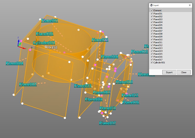
The KEYENCE XM and WM CMMs can build out geometries that can easily be translated into an STP file. Here we can see the overlay of the measured elements over an image of the part thanks to KEYENCE's augmented reality software capabilities, making visualization of reverse engineering simple.
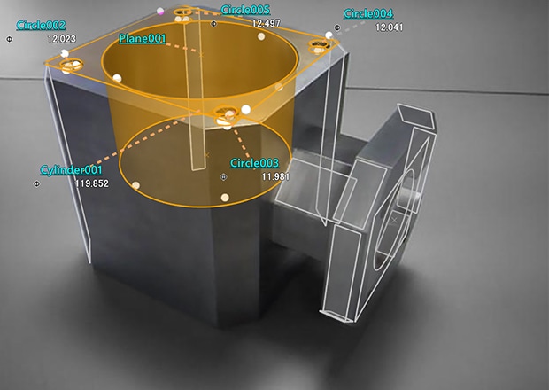
After measuring all relevant elements, these geometries can be exported as an STP file. A bit of clean up will be necessary in a third-party CAD software, like creating edges from the intersection of the planes. Once that is complete, you are left with a useful and highly accurate 3D model.

Related Products
Related Downloads
-
XM Series Handheld Probe Coordinate Measuring Machine Catalog
Brochure for the XM-5000 Series Handheld CMM. Portable CMM to easily and accurately measure 3D and GD&T features anywhere including the shop floor and in the machine tool.
-
WM-6000 series Wide Area CMM Catalog
Brochure for the WM-6000 series Wide-Area CMM. A portable setup with a wireless handheld probe that enables users measure large parts and equipment.
![WM-6000 series Measurement / Application Examples [System Versatility Examples]](/img/asset/AS_116820_L.jpg)