How to Assemble a Strain Gauge Bridge Circuit
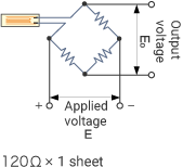
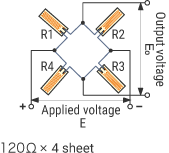
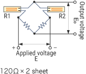
Bridge circuits refer to electric circuits configured to link four elements in a bridge-like manner, and typical types include Wheatstone bridges and meter bridges. In a bridge circuit, if the value of each element is balanced, the output voltage is “0” irrespective of the input voltage. Strain gauges use this property to measure strain. The way that the circuit is assembled varies depending on the measurement target, and different circuits are used for different measurement purposes.
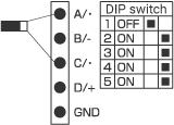
This section explains how to assemble a circuit and methods to connect to the strain measurement unit “NR-ST04.”
Tensile strain/compressive strain
One-gauge method, two-wire system
This is the most common connection method.
| Measurement example | Bridge circuit | Output | Temperature compensation |
Lead wire temperature compensation |
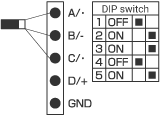
Wiring to the NR-ST04 |
|---|---|---|---|---|---|
 |
 |
1×
|
-
|
-
|
 |
One-gauge method, three-wire system
This method can cancel the temperature effect of the lead wires.
| Measurement example | Bridge circuit | Output | Temperature compensation |
Lead wire temperature compensation |
Wiring to the NR-ST04 |
|---|---|---|---|---|---|
 |
 |
1×
|
-
|
✓
|
 |
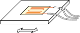
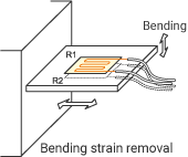
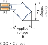
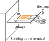
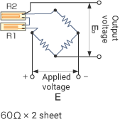
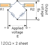
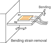
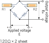
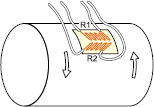
One-gauge method (two sheets), two-wire system
Two 60 Ω strain gauge sheets are connected in series. This method can cancel the bending strain.
| Measurement example | Bridge circuit | Output | Temperature compensation |
Lead wire temperature compensation |
Wiring to the NR-ST04 |
|---|---|---|---|---|---|
 |
 |
1×
|
-
|
-
|
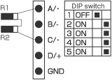 |
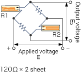
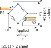
One-gauge method (two sheets), three-wire system
Two 60 Ω strain gauge sheets are connected in series. This method can cancel the temperature effect of the lead wires and the bending strain.
| Measurement example | Bridge circuit | Output | Temperature compensation |
Lead wire temperature compensation |
Wiring to the NR-ST04 |
|---|---|---|---|---|---|
 |
 |
1×
|
-
|
✓
|
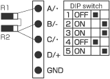 |
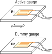
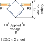
Two-gauge method, adjacent sides (active/dummy)
A reference strain gauge is attached to a test piece that is not subjected to stress and is made of the same material as the measurement target. The apparent strain that has occurred due to the temperature change is measured by the reference gauge and canceled.
| Measurement example | Bridge circuit | Output | Temperature compensation |
Lead wire temperature compensation |
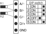
Wiring to the NR-ST04 |
|---|---|---|---|---|---|
 |
 |
1×
|
✓
|
✓
|
 |
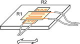
Two-gauge method, adjacent sides (two-active perpendicular arrangement)
One sheet containing two elements (two axes crossed) is attached. Output: (1 + Poisson’s ratio) times
| Measurement example | Bridge circuit | Output | Temperature compensation |
Lead wire temperature compensation |
Wiring to the NR-ST04 |
|---|---|---|---|---|---|
 |
 |
1 + ν
|
✓
|
✓
|
 |
Two-gauge method, opposite sides (two actives), two-wire system
Because the NR-ST04’s built-in bridge box does not support the opposite side, an external bridge box or two channels are used for calculation.
| Measurement example | Bridge circuit | Output | Temperature compensation |
Lead wire temperature compensation |
Wiring to the NR-ST04 |
|---|---|---|---|---|---|
 |
 |
2×
|
-
|
-
|
Method 1: Use an external bridge box. Connect the bridge box and the NR-ST04 with the four-gauge method.
Method 2: With the one-gauge method, two-wire system, connect two strain gauge sheets, one to CH1 and one to CH2. Calculation: (CH1 + CH2) |
Two-gauge method, opposite sides (two actives), three-wire system
Because the NR-ST04’s built-in bridge box does not support the opposite side, an external bridge box or two channels are used for calculation.
| Measurement example | Bridge circuit | Output | Temperature compensation |
Lead wire temperature compensation |
Wiring to the NR-ST04 |
|---|---|---|---|---|---|
 |
 |
2×
|
-
|
✓
|
Method 1: Use an external bridge box. Connect the bridge box and the NR-ST04 with the four-gauge method.
Method 2: With the one-gauge method, three-wire system, connect two strain gauge sheets, one to CH1 and one to CH2 Calculation: (CH1 + CH2) |
Four-gauge method (active/dummy)
A reference strain gauge is attached to a test piece that is not subjected to stress and is made of the same material as the measurement target. The apparent strain that has occurred due to the temperature change is measured by the reference gauge and canceled.
| Measurement example | Bridge circuit | Output | Temperature compensation |
Lead wire temperature compensation |
Wiring to the NR-ST04 |
|---|---|---|---|---|---|
 |
 |
2×
|
✓
|
✓
|
 |
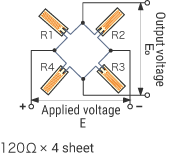
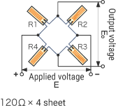
Four-gauge method (four-active perpendicular arrangement)
Two sheets containing two elements (two axes crossed) are attached. (Four gauges in total) Output: 2 × (1 + Poisson’s ratio) times
| Measurement example | Bridge circuit | Output | Temperature compensation |
Lead wire temperature compensation |
Wiring to the NR-ST04 |
|---|---|---|---|---|---|
 |
 |
2×
(1 + ν) |
✓
|
✓
|
 |

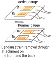
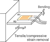
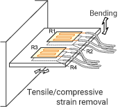
Bending strain
Two-gauge method, adjacent sides
Strain gauges are attached on the front and the back. This method enables strain measurement without being affected by tensile strain or compressive strain.
| Measurement example | Bridge circuit | Output | Temperature compensation |
Lead wire temperature compensation |
Wiring to the NR-ST04 |
|---|---|---|---|---|---|
 |
 |
2×
|
✓
|
✓
|
 |
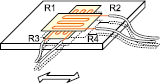
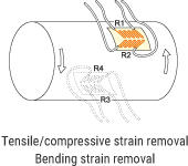
Four-gauge method
| Measurement example | Bridge circuit | Output | Temperature compensation |
Lead wire temperature compensation |
Wiring to the NR-ST04 |
|---|---|---|---|---|---|
 |
 |
4×
|
✓
|
✓
|
 |
Twisting strain
Two-gauge method, adjacent sides
Two strain gauge sheets are attached by tilting them ±45° against the axis (for two elements ±45° shear).
| Measurement example | Bridge circuit | Output | Temperature compensation |
Lead wire temperature compensation |
Wiring to the NR-ST04 |
|---|---|---|---|---|---|
 |
 |
2×
|
✓
|
✓
|
 |
Four-gauge method
| Measurement example | Bridge circuit | Output | Temperature compensation |
Lead wire temperature compensation |
Wiring to the NR-ST04 |
|---|---|---|---|---|---|
 |
 |
4×
|
✓
|
✓
|
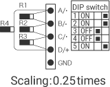 |
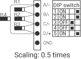
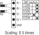
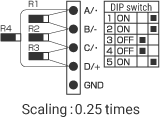
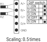
Scaling
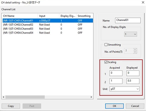
To obtain 0.5 times through scaling, configure the settings as shown above.

