Data Acquisition (DAQ)
Understanding CAN Data Protocols and Mechanisms
-
Tags:
- CAN Data
As an industry-standard fieldbus communication solution, the CAN protocol, which started as an automobile’s network communication system, has extended its use to other products and industries, including medical equipment, industrial automation systems, and DAQ applications.
What is the CAN Protocol?
The Controller Area Network or CAN protocol is a communication method between devices embedded in vehicles. It’s a decentralized network of communication, meaning devices can communicate without a host. It was designed by Bosch — a German engineering and technology company — and originally for automotive and aerospace industries, but later widely adopted in machine control, automation, and other industrial applications.
Basics in CAN Communication — “Dominant” and “Recessive”
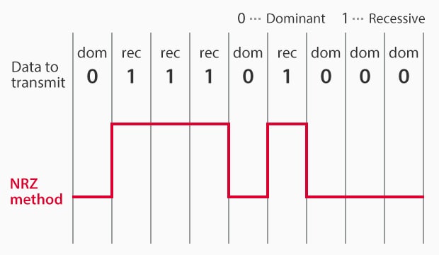
Non-Return-to-Zero (NRZ) method
In industrial applications, the CAN protocol allows various industrial system components, such as machines, sensors, and actuators, to communicate with one another. Data is converted to digital signals (0 and 1), with 0 called “dominant” and 1 called “recessive.” If both are transmitted simultaneously, the dominant takes priority. CAN also uses the Non-Return-to-Zero (NRZ) method for data conversion. Its overarching goal is to increase the safety and quality of automobiles, industrial machinery, and automation systems.
Key Features and Benefits of CAN Data Protocol
CAN provides a fast and easy way to create and maintain communication networks that are simple yet robust. CAN key features are:
- Reduced wiring systems
- High message frequency of more than 10,000/s
- High bandwidth utilization
- Flexible data transmission and reasonable transmission speeds
Especially for engineers who work with high-level industrial embedded systems, time, efficiency, and proper communication of devices are crucial. CAN protocols offer significant benefits to these professionals.
- Lower cost by driving down the need for complex wiring systems.
- Built-in error detection system that can spot errors and prevent faults from spreading.
- A robust communication protocol that can recover from errors on its own.
- Flexibility due to every device on the network having a separate CAN controller chip. This makes modification and corrections quick and easy with minimal overall system impact.

Common Applications of CAN Data Protocol
CAN Protocols find great use in networking applications requiring frequent, simple communication among connected devices. Here are some application examples.
Automotive Industry
- Used by car manufacturers for aftermarket vehicle and fleet tracking.
- Vehicle remote start and security applications.
Construction Industry
- Connecting elevator and escalator systems.
- Data transfer between access control nodes and secure door controllers.
- Connecting light control sensors and dimmers.
CAN Communication Unite “Frame”
CAN digital signals are grouped into four types or “frames”: data frame, remote frame, overload frame, and error frame.
Data Frame
The format for data transmission is called the “data frame.” There are two types of data frames: standard format and extended format.
Frame Structure in Standard Format
An explanation of the frame structure in “standard format” mainly used for CAN communication for automobiles is given below.
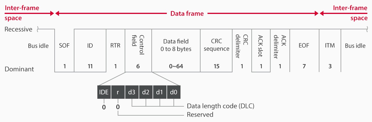
The values indicated here show the maximum bit length of each field. The upper line indicates recessive and the lower line indicates dominant. A field is fixed as dominant if a line is only shown for dominant. Similarly, a field is fixed as recessive if a line is only shown as recessive. If lines are shown for both dominant and recessive, it can vary depending on the transmitted data.
- SOF: The part to be transmitted first from the relevant note. This field is called “start of frame”, indicating the start position and is used for synchronization between nodes.
- ID: This field consists of 11 bits in standard format, 29 bits in extended. Determines data content, transmitter ID, and arbitration priority.
- RTR: The remote transmission request (RTR) field, which distinguishes between data frames and remote frames, is dominant for a data frame and recessive for a remote frame. As with the ID, this field is also used for arbitration.
- Control Field: Consists of the identifier extension (IDE) bit, the reserved bit “r” (1 bit each), and the 4-bit data length code (DLC).
- Data Field: The body of transmitted data is called the “data field.” The length varies between 0 and 8 bytes (0 to 64 bits) depending on the DLC setting, and the designer can determine what data is assigned.
- CRC Sequence: The transmitting node calculates the values to transmit for the SOF, ID, control field, and data field, and it transmits the results as the cyclic redundancy check (CRC) sequence. The receiving node also conducts the same calculation to determine if it has received the data properly.
- CRC Delimiter: Indicates the end of the CRC sequence. The combination of CRC sequence and CRC delimiter is called the CRC field.
- ACK Slot: Verifies if the data has been received correctly.
- ACK Delimiter: Indicates the end of the ACK slot. The combination of the ACK slot and ACK delimiter is called the ACK field.
- EOF: The end of frame (EOF) field is transmitted at the end of a data frame.
- ITM: Intermission, indicating bus idle state, not part of the data frame.
Frame Structure in Extended Format
Used by large vehicles for CAN communication, differing in ID to RTR fields:
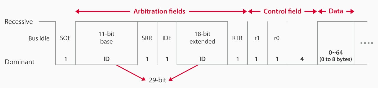
Extended format
- Base ID: Equivalent to the standard format ID.
- SRR: 1-bit recessive substitute remote request.
- IDE: 1-bit recessive identifier extension.
- Extended ID: Combines 11-bit standard ID with 18-bit extended ID, providing ~5.4 million identifiable types.
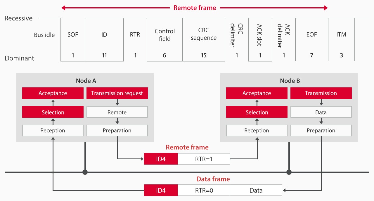
Remote Frame
In CAN communication, a node that will request certain data transmits a remote frame, and then the node that has the data returns a data frame. A remote frame is structured by deleting a data field from a data frame (or, by setting the DLC and data field to 0 bytes). The RTR is set to recessive to identify a remote frame (it is set to dominant in a data frame). However, to reduce the data occupancy ratio, remote frames have hardly been used in recent years. Instead, data frames are regularly transmitted to each node, in general.
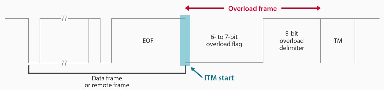
Overload Frame
In the days after CAN came into existence, the processing capacity of microcontrollers and CAN controllers was low, so the “overload frame” was developed to address this problem. The main role of this frame is to be transmitted to a node that is slow in processing a data frame, thereby delaying the start of transmission of the next data frame.
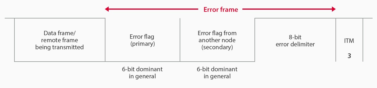
Error Frame
This frame is transmitted when a communication error (among the various types of communication errors) occurs, thereby indicating this occurrence on the CAN network.
What is the OSI Basic Reference Model?
The Open Systems Interconnection (OSI) is a reference model that describes the transfer of data within devices in a network. The purpose of the model is to guide developers in developing products that interoperate in a clear framework. The OSI is a seven-layer model, with each layer representing a distinct aspect of network communication. The layers are:
- Application
- Presentation
- Session
- Transport
- Network
- Data Link
- Physical
The relationship between CAN and the OSI model is that CAN is a network type that focuses only on the last two layers — Physical and Data Link. The Physical layer defines how wires, connectors, and other physical connections are made. The Data Link aspect focuses on how data is packaged and sent over a network.
How Do We Measure Acceleration with CAN?
Measuring acceleration with CAN protocol typically follows a five-stage process and requires three instruments. The measuring devices required are:
- An acceleration sensor
- A CAN node - dedicated IC or a microcontroller
- A CAN transceiver
Overview of Measurement Stages
- The accelerometer uses its sensor to measure acceleration and generate an analog signal.
- The CAN node converts the generated analog signal to a digital signal.
- The CAN node encodes and sends the digital signal into a CAN frame format.
- The CAN node transmits the frame using the transceiver.
- Other CAN nodes receive the frame. They can then use the acceleration data for monitoring, logging, or other purposes.
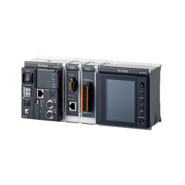
KEYENCE offers a line of measurement DAQ devices or data loggers that support CAN communications. These DAQ Acquisition systems can acquire data, such as temperature, pressure, and flow rate, from CAN devices.
Advantages of Using CAN for Data Measurement
Using a Controller Area Network in data measurement offers many benefits. They include:
- A multi-node function that allows data collection from multiple devices or sensors
- Cost-effective solution offering reduced wiring and hardware configuration
- CAN speed data transfer of up to 1 Mbps
- Built-in error detection and correction to ensure data integrity
How CAN Communication Works
CAN communication operates on a bus structure with multiple devices or nodes connected to the same network. Each node has a unique identifier and can send and receive messages through the bus.
When a device wants to transmit data, it first checks if the bus is available. If it is not, it waits for a random amount of time before trying again. This helps prevent collisions between messages sent by different nodes.
Once the bus is available, the transmitting node sends its message along with its identifier. For any other nodes receiving this message, check if their identifier matches the one transmitted. Only those that match will receive and process the message.
High-Speed vs. Low-Speed CAN
There are different sublayers in the physical layer of CAN. The high-speed and low-speed CAN sublayers are described below:
High-Speed CAN
Also referred to as ISO 11898-2 or CAN C, High-speed CAN supports a transfer rate of up to 1 Mbit/s and is implemented with two wires. Some high-speed CAN devices are engine control modules, antilock brake systems, and emissions systems.
Low-Speed CAN
Also called CAN B or ISO 11898-3, low-speed CAN networks support a transfer rate of up to 125 kbit/s and are implemented with two wires as well. Typical low-speed CAN applications are wires that pass through a vehicle’s door, seat control modules, and other comfort devices in automobiles.
CAN FD
Controller Area Network Flexible Data-Rate (CAN FD) is Bosch’s second-generation CAN protocol. It offers much larger frame sizes and improved data transfer. As an extension of the original CAN bus protocol, it supports up to 64 data bytes per frame compared to the eight data bytes supported in the first-gen CAN.
CAN FD offers better error detection than the classical one and uses cyclic redundancy check (CRC) to reduce cases of undetected errors.
Protocols Built on CAN
Below are some protocols built on CAN:
- J1939: used for vehicle communication in the automotive industry.
- NMEA2000 (N2K): used for both communication within ships and boats.
- CANopen: found in automation embedded systems.
- DeviceNet: used for device communication in industrial automation.
- CAN Kingdom: used for device communication in industrial automation applications.
Industrial Automation Applications
CAN provides many benefits when it comes to application in industrial automation. Below are ways in which CAN is used in factory automation:
- Production line control and monitoring
- Robots, CNC, and other tools control
- Conveyor, sorting, and other material handling systems
- Quality control and inspection systems
- HVAC and lighting automation systems
- Temperature monitoring systems for logistic problems
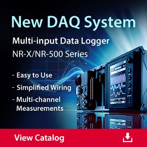
KEYENCE offers a line of DAQ systems that can be used in different industrial and automation applications. These portable data acquisition systems can accurately measure all types of data input, providing real-time measurements and inspections.
Have more questions about DAQ hardware solutions? Contact us today.