Important Knowledge for Strain Measurement
The strain of an object is measured using a strain gauge, and a strain gauge needs to be selected according to the measurement target. This section introduces how to select a strain gauge and key points for improving the accuracy of strain measurement.
Key points for selecting a strain gauge
Select a strain gauge that suits the material of the measurement target
Select a strain gauge that suits the material of the measurement target to cancel the effect of the temperature change (thermal expansion) of the target.
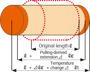
For general steel materials, the length changes by 11 μm (that is, 11 μST) per meter with a temperature change of 1°C (1.8°F).
This apparent strain εtemp is expressed as follows, where the linear expansion coefficient of the target measurement is β, the linear expansion coefficient of the strain gauge is βG, the temperature coefficient of the strain gauge resistor is αG, and the gauge factor is K.
εtemp = (β − βG) + αG/K
- Examples of linear expansion coefficients
- Steel material: 11.7 × 10⁻⁶/°C (°F)
- SUS304: 16.2 × 10⁻⁶/°C (°F)
- Aluminum alloy: 23.4 × 10⁻⁶/°C (°F)
Hence, select a gauge whose linear expansion coefficient for the material of the measurement target has been corrected to make the apparent strain εtemp “0.” For general strain gauges, the type is suffixed with the integer part of the linear expansion coefficient, such as “11” and “16.”
Select a strain gauge whose length and width match your measurement purpose
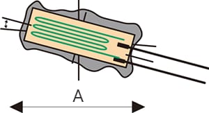
Select a strain gauge whose length and width are suited to the material of the measurement target and your measurement purpose. For example, use a narrow strain gauge for narrow measurement targets such as pipes and round bars.
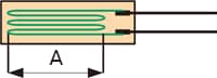
- A
- Gauge length
- Examples of gauge lengths for different measurement purposes
- For surfaces subject to high-speed phenomena such as shock, round surfaces, and surfaces under stress concentration: 0.2 to 1 mm
- For measurement of metals and plastics: Approximately 2 to 10 mm
- For measurement of wood and composite materials: Approximately 10 to 20 mm
- For measurement of concrete: 30 mm or longer (3 times or more the gravel particle size)
Select a strain gauge that satisfies the applicable conditions such as installation environment and wiring length
General foil gauges are made of “advanced alloy,” an alloy containing 54% Cu and 46% Ni, and are several micrometers thick. For the base part, polyester and polyimide are used. As such, use a dedicated strain gauge when watertightness and high temperature resistance are required.
If you want to enhance the measurement accuracy
Click here for key points for improvement.

Key points for realizing accurate measurement
Check the attachment status of the strain gauge
Have you properly completed the “preprocessing” for attachment described in “Basics of Strain Measurement”? Have you dropped a sufficient amount of adhesive on the back of the strain gauge? Check the following points to make sure that the strain gauge has been attached properly.
Whether the adhesive has overflown properly
Check whether the adhesive has overflown evenly. The gauge is unlikely to have been attached firmly in places where the adhesive has not overflown.
Whether the attached surface is free of dust and bubbles
Measurement errors are caused if dust or bubbles have been left on the surface before attachment.
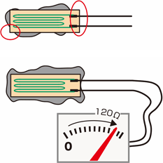
Whether the lead wires are broken
The lead wires of a strain gauge are extremely thin and may be broken if force is applied during attachment. Measure the resistance between the two wires of the gauge with a tester. They are not broken if 120 Ω is indicated.
Correct the gauge factor of the strain gauge
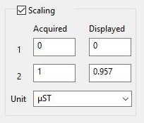
Although strain gauges have been manufactured with a reference gauge factor of 2.00, the actual factor is approximately 1.9 to 2.2. Because the gauge factor of a strain recorder is fixed at 2.00, a 0.1 difference in the gauge factor will lead to an error of approximately 5%. As such, correction with the scaling function of the recorder must be performed by using the gauge factor K described on the box of the strain gauge.
- ε0:
- True strain
- ε:
- Measured strain
ε0 = ε × 2.00/K
■ Correction example
When using a strain gauge having a gauge factor of 2.09
ε0 = ε × 2.00/K = ε × 2.00/2.09 = 0.957 × ε
Correct the angle error
- A
- Tensile direction
A 5° difference between strain and strain gauge directions causes an error of approximately 1%. If the direction of attachment does not match the scribed lines, perform scaling and correction using a Poisson’s ratio (v).
- ε0:
- True strain
- ε:
- Measured strain
- ν:
- Poisson’s ratio
- θ:
- Angle (°)
ε = ε0 {(1 − ν) + (1 + ν) cos2θ)}/2
Because Poisson’s ratios are generally around 0.3,
ε = ε0 (0.7 + 1.3 cos2θ)/2
ε0 = 2ε/(0.7 + 1.3 cos2θ)
Reference: Angle-based sensitivity errors with a Poisson’s ratio of 0.3
1° = 0.03%, 2° = 0.16%, 3° = 0.36%, 4° = 0.64%, 5° = 1.00%
Correct the effect of the wiring length
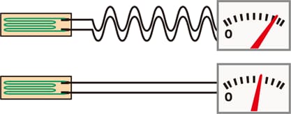
If the lead wires are extended, the effect of their wiring resistance is generated. For thin wires, extension by 20 m generates an error of approximately 7%. For a long wiring length, perform scaling and correction using the following formula.
- ε0:
- True strain
- ε:
- Measured strain
- γ:
- Lead wire resistance (round-trip)
ε0 = ε (1 + γ/R)
■ Reference:
Relationships between the nominal cross-sectional area of a lead wire and the resistance (round-trip) per meter
0.08 mm2->0.44 Ω
0.18 mm2->0.2 Ω
0.3 mm2->0.117 Ω
0.5 mm2->0.07 Ω
0.75 mm2->0.047 Ω
Correct the temperature effect
To achieve accurate measurement in an environment with temperature change, it is necessary to use a self temperature compensating-type strain gauge or to compensate the temperature using the two-gauge method. For a long wiring length, the three-wire system offers better measurement accuracy.
If you want to enhance the measurement accuracy
Click here for key points for improvement.

