Strain Analysis Improvement
Because noise greatly affects the accuracy of measurement, the characteristics and capacity of noise cut filters have a great importance. This section explains filters that cut high frequency noise caused by dynamic strain. This section also introduces the gauge factor, which expresses the sensitivity of a strain gauge, and “auto balance.”
Low-pass filters
To cut high frequency noise unnecessary for dynamic strain measurement, it is indispensable to set a low-pass filter. As a filter for a dynamic strain amplifier, a Bessel or Butterworth filter is generally used.
Characteristics of Bessel filters
- Good transient response (rising/falling) characteristic
- Small overshoot and ringing
Characteristics of Butterworth filters
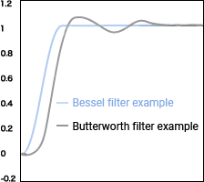
- Easy to configure a circuit
- Generality
Thanks to their good transient response characteristic and small overshoot and ringing, Bessel filters are suited to applications in which waveforms matter, such as analog signals.
Filter capacity
As the filter capacity, the attenuation rate when a frequency an octave away is input is expressed in decibels (dB).
The higher the filter order, the higher the attenuation rate. However, a higher filter order also leads to larger overshoot and ringing, so filters at several orders are generally used.
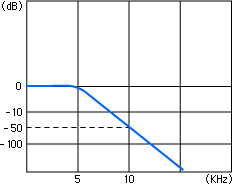
An octave is double the frequency.
Meanwhile, because the attenuation rate is indicated as
−3 dB = Approx. 0.7 times
−20 dB = Approx. 0.1 times
−30 dB = Approx. 0.03 times
if the cutoff frequency is set to 5 kHz,
an input of 10 kHz, 1 V is filtered to 0.03 V or lower at −30 dB/oct.
Click here for strain measurement examples in each industry.

Gauge factor correction and auto balance
An output voltage value from a strain gauge
In strain measurement, the value called the “gauge factor” plays an important role.
First, let’s check the magnitude of the output voltage of a strain gauge.
The figure below shows a wiring diagram for the one-gauge method.
It has been described earlier that when there is no strain, the circuit is in a balanced condition, so the voltage e is 0 V.
If strain occurs, the voltage e is expressed as follows.
e = 1/4 × E × Ks × ε — (1)
E: bridge power voltage, Ks: gauge factor, ε: strain amount
Incidentally, a general formula not limited to the one-gauge method is as follows.
e = 1/4 × Ks (ε1 − ε2 + ε3 − ε4) E
Gauge factor
“Ks” in formula (1) above is a constant of proportionality called the gauge factor.
The true gauge factor is generally determined to be 2.0.
(In practice, the actual gauge factor varies and is described on the box of each gauge.)
In addition, the bridge power supply is also generally 2 V.
You can see the reason through calculation. Let’s assign values to formula (1), given above.
e = 1/4 × E × Ks × ε — (1)
↓ (Assign E = 2 V and Ks = 2.0)
e = 1/4 × 2 × 2 × ε = ε
As shown above, you can measure the strain amount through direct reading.
This is very useful.
Gauge factor correction
Although strain gauges have been manufactured with a reference gauge factor of 2.00, the actual factor is approximately 1.9 to 2.2.
Because the gauge factor of a strain recorder is fixed at 2.00, a 0.1 difference in the gauge factor will lead to an error of approximately 5%.
As such, correction with the scaling function of the recorder must be performed by using the gauge factor K described on the box of the strain gauge.
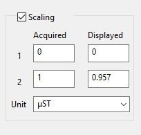
ε0 = ε × 2.00/K
ε0: true strain amount, ε: measured strain amount
When using a strain gauge having a gauge factor of 2.09
ε0 = ε × 2.00/K = ε × 2.00/2.09 = 0.957 × ε
Auto balance
Be sure to perform auto balance adjustment before starting strain measurement. When a strain gauge comes into contact with a measurement target, the strain gauge is strained, although only slightly.
Auto balance is intended to cancel this strain amount to treat a measured value in no load state as 0.
Click here for strain measurement examples in each industry.

