Basics of Strain Measurement
A strain gauge is designed to measure the strain amount by using the principle that the resistance changes with the expansion/contraction of the strain gauge. Then, how does the gauge detect that change in the resistance? Here, let’s dig a little deeper into strain measurement.

Bridge circuit, a must in strain measurement
A circuit that detects a minute change in the resistance and outputs it as a voltage change is called a “Wheatstone bridge.”
(In strain measurement, this circuit is simply called a “bridge.”)
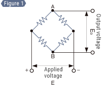
In a bridge circuit, four resistors are connected in a rectangular configuration as shown in Figure 1.
If a voltage of E (V) is applied from the bottom of the circuit and the resistance of these four resistors is exactly the same, the voltage is equal at points A and B, and the output voltage Eo becomes the difference between A and B, namely, zero.
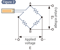
Next, let’s replace one of the resistors with a strain gauge as shown in Figure 2.
If the strain gauge has the same resistance as the other three resistors, the conditions are the same as in Figure 1, so the output voltage Eo is 0 V. If a strain is applied to the strain gauge and a change of ΔR occurs in its resistance, the balance is lost and a voltage difference occurs between points A and B. This voltage difference is measured to obtain the strain.
Summary
The relationship between output power Eo and strain ε is expressed as follows. From
Eo = (1/4) × (ΔR/R) × E — Formula 7
From formula 6
(ΔR/R = constant of proportionality (gauge factor) K × ε):
Eo = 1/4 × K × ε × E — Formula 8
Thus, the strain amount can be converted to a voltage.
Relationship between output voltage and strain amount
Let’s continue using the above example for the following explanation.
Since the gauge factor K is generally around 2, by assuming that the factor is 2.00 and the applied voltage is 2.00 V,
the strain ε and the output voltage Eo are as follows from formula 8.
Eo = 1/4 × 2.00 × ε × 2.00 V
Eo = ε
Therefore, a strain amount of 1000 μST causes a reading (= voltage value) of 1000 μV (1 mV) on the instrument.
Click here for strain measurement examples in each industry.

Attaching a strain gauge
Next, let’s start a practical measurement by actually attaching a strain gauge. Prepare a proper metal plate and a strain gauge before proceeding. For the instrument, the following explanation uses the KEYENCE dynamic strain measurement unit NR-ST04.
Preprocessing
- A
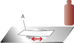
- Wipe the metal plate thoroughly
with a cloth soaked with acetone.
If there is any rust or paint on the position where the strain gauge will be attached, this rust or paint will slide between the strain gauge and metal plate. Because this issue prevents accurate measurement, prepare a surface that is appropriate for attachment.
- Expose the metal line using a grinder, a blasting device, or the like.
- To make the surface smooth, use sandpaper (grit around 200 to 300) to polish an area slightly wider than the strain gauge.
- Using clean cloth (or something similar) soaked with acetone, degrease and clean the polished surface until the cloth does not get dirty anymore.
Determining the attaching position

- A
- Ruler
Use a pencil (having a hardness of approximately 4H) to accurately scribe the position at which to attach the gauge. Mark the position with a cross shape so as to show the center and the direction.
Attaching the gauge
- A
- Polyethylene sheet
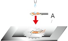
Drop an appropriate amount of adhesive on the back of the strain gauge and attach it in accordance with the scribed lines. Use the adhesive provided by the manufacturer of the strain gauge.
Put a polyethylene sheet over the strain gauge and press down on it with your fingers for about one minute.
Wait for the assembly to completely harden before starting measurement.
Which is the back of a strain gauge?
The front side has a soldered lead wire and also shows a pattern clearly.

The back side is a flat film surface that is transparent enough to see the pattern.
Wiring an instrument and configuring its settings
Fixing the lead wires in place

- A
- Fixing the lead wires in place
Any movement of the lead wires of the strain gauge during measurement causes measurement errors, so fix the lead wires in place with tape, a cable tie, or a similar method in a way that does not apply stress to the gauge body.
Wiring to an instrument
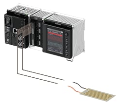
For the instrument, the following explanation uses the KEYENCE dynamic strain measurement unit NR-ST04. Wire the two lead wires of the strain gauge to the A/• and C/• terminals of CH1, respectively. There is no positive and negative polarity. Make sure that DIP switch 1 on the front of the instrument is set to OFF and DIP switches 2 to 5 are set to ON.
Measurement settings
The KEYENCE dynamic strain measurement unit NR-ST04 enables measurement not only on its own but also with your PC connected to it via USB. Explanations of the two ways to configure the settings required for measurement: measurement with a connected PC and direct measurement on the measurement unit, are given below.
Setting example for measurement with a connected PC
- Click [Acquisition Settings].
![Click [Collection Settings].](/Images/s_measurement_010_1878240.gif)
- Select “±2000 μST” for [Input range] and click [Next].
![Select “±2000 μST” for [Input range] and click [Next].](/Images/s_measurement_011_1878241.gif)
- Select “1 ms” for [Sampling cycle] and click [Finish].
- Before starting measurement, click [Auto balance] to correct the minute distortion that occurred on the strain gauge when it was attached.
![Before starting measurement, click [BAL] (the auto balance adjustment button) to correct the minute distortion that occurred on the strain gauge when it was attached.](/Images/s_measurement_012_1878242.gif)
- Click [Start].
![Click [Start Collection].](/Images/s_measurement_013_1878243.gif)
Setting example for direct measurement on the measurement unit
- Press the MENU key to display the [Acquisition and display] screen, and then select [Acquisition Setting]. Select [Unit & channel setting] and set the input channel for unit “ST04.” Press the F1 key to return to [Acquisition Setting].
![Press the MENU key to display the [Collection and Display] screen, and then select [Collection Settings]. Select [Settings of Unit and Each Channel] and set the input channel for unit “ST04.” Press the F1 key to return to [Collection Settings].](/Images/s_measurement_014_1878244.gif)
- Select [Collection Condition Settings] and set [Sampling cycle] to “1 ms.”Press the MENU key and then the F1 key to confirm your settings.
- From [Initial Adj], select [Auto balance] to enable auto balance and press the MENU key to execute it.
![From [Initial Adjustment], select [Auto Balance] to enable auto balance and press the MENU key to execute it.](/Images/s_measurement_015_1878245.gif)
- Press the START/STOP key.
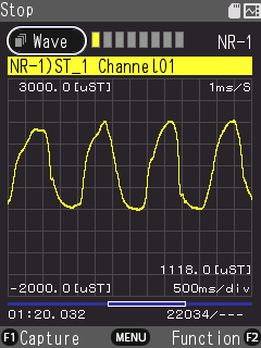
Has the waveform changed after you applied a strain to the strain gauge?
Click here for strain measurement examples in each industry.

