Relationship between Pulse Signal and Rotation Speed
Pulse signals are highly compatible with digital circuits and are used for motor control signals, engine speed data, and the like. This section explains the characteristics of pulse signals and the differences in the characteristics using motors as examples.
Pulses used to identify or control motor rotations
Broadly classified, there are two typical applications of pulses: measurement of speed, distance, etc. using input pulses and control of systems such as motors and inverters by outputting pulses. Both of these types of applications are related to the element of “rotation.”
Click here for application examples where measurement is possible using pulses.
Rotation speed measurement using pulses
Typical methods to measure the rotation speed of a motor or the like using pulses include measurement using a stroboscope, measurement using a tachometer, and measurement using an optical instrument.
Measurement using a stroboscope
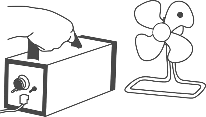
A stroboscope is an instrument that repeatedly emits instantaneously generated light at specific intervals. When a stroboscope is used to shine light on a rotating object at equal time intervals, the object appears to be stopped if the flashing and rotation cycles match, even if the object is rotating at too high of a speed to be visually inspected in a general manner. The stroboscope method is a way to obtain the rotation speed using this phenomenon and is used not only for engine and motor speed measurement but also for inspection of defects such as scratches and chips on rotating objects.
Measurement using a tachometer
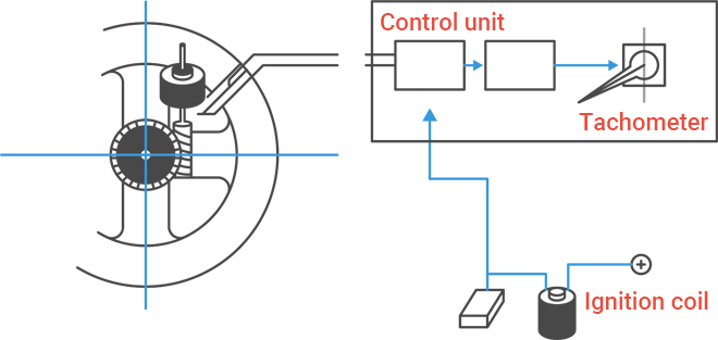
Tachometers are designed to measure the rotation speed of machines such as engines and motors and are classified into mechanical and electrical types according to the way that they read the speed. Today, most automobiles are equipped with electrical tachometers. The electrical type counts the ignition pulses of the ignition coil to obtain the speed. This type is mainly used to identify the engine speed of automobiles and motorcycles.
Measurement using an optical instrument
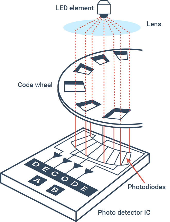
This method obtains the rotation speed by using light emitting diodes or similar devices to shine infrared light on a rotating disk that has fine slits and holes and sending the light that passes through the slits and holes to photodiodes to convert mechanical rotation displacement to pulse signals. In addition to the automotive and aerospace industries, this method is also utilized in the energy industry.
Motors that use pulses
Typical systems that control driving using pulse signals include various types of motors such as stepping motors (pulse motors) and servo motors.
Stepping motor
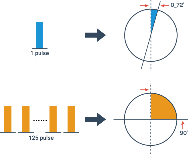
This is a motor that operates in synchronization with the electric power of the received pulse signals. This motor controls the angle, speed, etc. of rotation according to the number of pulses and the frequency. This motor has a predetermined shaft rotating angle per pulse (the “basic step angle”) and is designed to rotate by that angle every time it receives a pulse. A standard 5-phase type has a basic step angle of 0.72°, which means rotation by 90° with 125 pulses and by 360° with 500 pulses. The quantity of rotation of a stepping motor is proportional to the number of pulse signals, while the speed is proportional to the frequency.
Servo motor
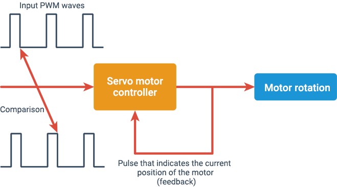
This is a motor that uses an automatic control unit “servo mechanism” that operates in reference to the position, direction, etc. of the target as the control input. A servo motor has a built-in rotation detector, which is not provided for a stepping motor, and feeds the rotation angle and speed it has detected to the driver. For its operation, the motor compares the current position of the rotation shaft with the target position to make the difference “0.” As such, this motor has an extremely high stopping accuracy and is commonly used for machine tools and industrial robots.
Differences in the characteristics
| Stepping motor | Servo motor | |
|---|---|---|
| Advantages |
|
|
| Disadvantages |
|
|

