Data Acquisition (DAQ)
Radiation Thermometers: Non-Contact Temperature Measurement
-
Tags:
- Data Acquisition , Temperature
This page introduces the basics of radiation thermometer measurement, the science behind these devices, the various types, and what they are designed for.
What is a Radiation Thermometer?
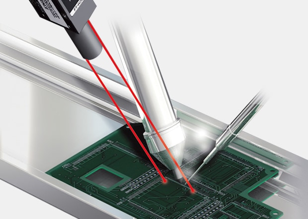
A radiation thermometer measures temperature without touching the object. Instead, it detects infrared radiation coming from the surface to determine how hot or cold something is. Unlike contact thermometers, these devices provide fast and precise temperature readings without physical contact, making them ideal for high-temperature, moving, or sensitive applications.

The Science Behind Radiation Thermometry
All objects emit infrared radiation, and the intensity of this emission increases with temperature; radiation thermometers detect this thermal radiation and then convert it into a temperature reading. They typically focus on wavelengths in the 8 to 14 µm range, where interference from water vapor and carbon dioxide is minimized.
Radiation thermometers work based on black body radiation. Any object above absolute zero emits thermal energy, and as its temperature rises, it releases more infrared radiation. In extreme heat, some objects even begin to glow, emitting visible light. By analyzing this radiation, a thermometer can accurately determine the object's surface temperature.
How Radiation Thermometers Work
A radiation thermometer uses an optical system to collect infrared radiation and focus it onto a sensor, such as a thermopile or pyroelectric detector. The sensor absorbs the infrared energy, converting it into an electrical signal that is processed into a temperature reading.
Other Elements of a Radiation Thermometer:
- Field of View (FOV) & Distance-to-Spot Ratio (D:S): A thermometer measures the average temperature within its FOV. A higher D:S ratio allows for accurate readings from farther distances.
- Emissivity Adjustments: Reflective surfaces, such as polished metals, may require emissivity adjustments or blackbody reference methods to ensure accuracy.
- Environmental Factors: Dust, humidity, and water vapor can scatter or absorb infrared energy, affecting measurements. A clean lens and air purging systems improve accuracy.
- Angled Measurements: If used at an angle exceeding 45 degrees, accuracy may decline due to reflected radiation.

Types of Radiation Thermometers
Radiation thermometers come in several forms, each suited to different applications. The most common types include:
Infrared Thermometers
These devices use infrared radiation to measure temperature without contact; their speed and accuracy make them essential in manufacturing, electronics, and medical applications. If you are interested in infrared temperature measurement, please check out the FT Series from KEYENCE!
Optical Pyrometers
Designed for high-temperature environments, these thermometers rely on visible light and infrared energy to measure extremely hot objects such as molten metals.
Ratio (Two-Color) Pyrometers
These thermometers compare two infrared wavelengths for improved accuracy, making them effective in harsh environments where dust, smoke, or changing emissivity might interfere with single-wavelength readings.
Fiber Optic Radiation Thermometers
Ideal for confined spaces or areas with intense electromagnetic interference, these thermometers use fiber optics to transmit infrared radiation to a remote detector.
Infrared Thermometers
Infrared (IR) thermometers are the most widely used measuring temperature devices in non-contact temperature measurement. These thermometers use a lens to focus infrared energy onto a sensor where it is then converted into an electrical signal. The device then processes this data to calculate an accurate radiation measurement. They work from a distance, allowing safe measurements in hazardous or hard-to-reach areas.
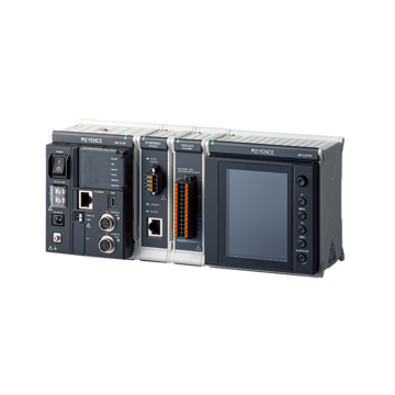
Find your ideal thermometer today and explore all of KEYENCE’s products that work with thermometers, such as the data logger NR-X.
Contact us today!