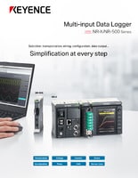
Data Acquisition (DAQ)
Selecting the Sampling Cycle for Voltage Measurement
-
Tags:
- Voltage
Accurate voltage measurement, in part, depends on selecting a measuring system with the right sampling rate. An acceptable sample rate is one of the elements that prevents data from being lost while conducting analog-to-digital measurements. For example, if the sampling rate is too slow, a peak measurement could be totally missed. With correct measurements, engineers, managers, and medical professionals are equipped with valuable information to make data-driven decisions. In voltage measurement, there is also the consideration of resolution versus accuracy. Lower resolution results in decreased measurement accuracy, so it is important to select appropriately based on your measurement objectives.
Understanding the Sampling Cycle
Part of the process required to get accurate measurements in data acquisition is the conversion of analog signals to digital form. Continuous waveforms are analyzed at various times and converted into digital samples. The sampling rate or cycle is determined by the amount of times per second the waveform is measured. The higher the sampling rate, the greater the frequency that can be recorded. The sampling rate should be at least ten times 10x the amount of the highest frequency component of the signal to avoid aliasing.
The sampling rate indicates how often conversion takes place. Calibrating voltage measurement equipment or devices to be in tune with the analog frequency being captured helps in detecting system anomalies. It can also impact decisions related to the implementation of corrective actions.
| Sampling Frequency/Signal Waveform Frequency | Effect on Recorded Waveforms |
|---|---|
|
Sampling Frequency/Signal Waveform Frequency
10x or more
|
Effect on Recorded Waveforms
Waveforms can be displayed and recorded accurately.
|
|
Sampling Frequency/Signal Waveform Frequency
Between 2x and 10x
|
Effect on Recorded Waveforms
Peak values become smaller. Waveforms become rougher.
|
|
Sampling Frequency/Signal Waveform Frequency
Less than 2x
|
Effect on Recorded Waveforms
Aliasing occurs, resulting in waveforms that are completely different from the actual ones being displayed.
|

Why is Voltage Measurement Important?
Voltage measurements offer an energy “picture” of an electric circuit. It provides information about power being dissipated in different parts of a circuit. When converting analog waveforms to digital data, captured signals are converted to discrete-time digital signals. In other words, the measuring device creates “snapshots” or series of discrete values at precise points. This process assists in converting analog signals to a format that’s readable for digital measurement systems.
Why Accurate Voltage Measurement Matters
The accuracy of a voltage measurement device or instrument relates to how closely a measurement is to an actual value. In appliance manufacturing, incorrect voltage measurement can lead to heat generation, resulting in potential fire outbreak. In other industries and applications, inaccurate measurement can cause equipment malfunction and underperformance.
Sampling at 1 kHz
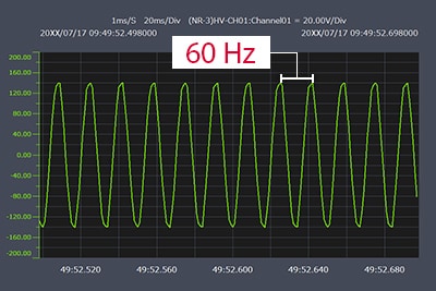
Waveforms can be measured accurately.
Sampling at 100 Hz
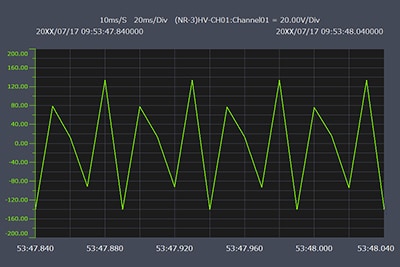
Waveforms cannot be measured accurately due to a slow sampling cycle.
Sampling at 10 Hz
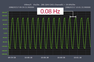
Fake waveform
Although the waveform may appear to be correct, aliasing has occurred, resulting in a completely different waveform with a cycle of 0.08 Hz.
Accurate voltage measurement in DAQ systems helps to zero in on the exact voltage of equipment or devices, ensuring precise calibration and troubleshooting. These devices could be inverters, storage batteries, solar cells, etc.

Importance of Voltage Measurement in Data Acquisition
In the automotive industry, engineers use voltage measurement devices to measure and monitor voltage changes in electronic components of vehicles. This lets them discover potential issues on time and enhance system performance.
In the energy sector, accurate voltage measurement helps regulate and control power generation and distribution. Voltage fluctuations in power grids can be detected and monitored. This facilitates effective energy management.
In the healthcare sector, precision voltage measurement helps medical professionals monitor patient health. Electroencephalogram devices measure “voltage signals” in the brain to help diagnose neurological issues. Machines like electrocardiograms (ECG or EKG) can help diagnose issues and inform the choice of treatment options. Both technologies and many more rely on accurate voltage measurements.
Applications in Various Industries
The benefits of the sampling cycle principle in different industries cannot be overemphasized:
- Reliable Data Storage: If analog signals can’t be converted to discrete data, storing and retrieving data long-term becomes challenging. This is because analog data is continuous and can’t be stored directly.
- Digital Processing: Without the process of the sampling cycle, analog signals cannot be processed or analyzed using digital means.
- Improved Automation Systems: While analog signals can be used in systems like analog actuators and proportional control without conversion, they have limitations. To enjoy modern automation systems that contribute immensely to everyday life, analog-to-digital conversions are needed.
Types of Voltage Measurement Solutions
Devices used to measure voltage range from conventional measuring devices to newer, advanced systems. The choice of instrument will depend on the industry and application requirements. Below are some common examples of voltage measurement devices.
- Voltmeter: A device that measures the electric potential difference (PD) between two points.
- Multimeter: A multimeter is a device used to measure multiple properties, including current, resistance, and voltage.
- In large-scale industrial measurements, conventional measuring tools may not be suitable, so there is a need for advanced measuring systems.
- Oscilloscopes: Electronic instruments used to observe and measure the waveform of electrical signals at high speed. They are suited for short-term observation and are mainly used for waveform display and sampling speed.
- High-Speed Waveform Recorder: Instruments that can record waveforms, often with high sampling rates and resolution. They are designed to capture glitches, waveforms that change at mid-speed, or other fleeting changes not visible on a traditional oscilloscope. They can also be used to measure vibration, control signals, and voltage in similar applications.
- Data Loggers: Also called Data Acquisition systems, data loggers are devices that can record different types of parameters, including current, temperature, and voltage. Data logger voltage measurement or real-time DAQ devices can be deployed for voltage measurement in R&D and manufacturing sites.
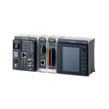
KEYENCE offers portable data acquisition systems that are lightweight, compact, scalable, and compatible with PCs. These solutions will perform in many different use cases.
Applications of Voltage Measurement Solutions
Voltage measurement solutions can be used in the following situations:
R&D Applications
- Data collection when performing on-vehicle testing in the automotive industry
- Displacement measurement during tension testing in the metal and plastic industry
- Evaluation of lithium-ion batteries in the electronic device industry
Production Site Applications
- Temperature measurement of bottles after sterilization in the food industry
- Multi-data collection for extruders in the metal and steel industry
- Data collection for processing machine tool run-out and vibration in the metal and automotive industry
Signal Conditioning
Signal conditioning is an important aspect of voltage measurement solutions that aims to prepare the voltage signal for measurement. This process includes filtering and amplification which helps ensure reliable and accurate measurement.
Another related aspect is the calibration and maintenance of the measurement devices or instruments. These checks and calibrations are important to maintain the reliability of the instruments and may include checking for noise, drift, and other potential problem sources.
How to Choose the Right Voltage Measurement Solution
Measuring voltage with the right equipment is important to get accurate voltage measurements. Consider such factors as sampling cycle, number of channels, resolution, and other factors relevant to the intended operation.
KEYENCE Data Acquisition systems are suitable for measuring needs and requirements. For example, the NR Series multi-input Data Logger has a sampling cycle of 10 Hz to 1 MHz, making it versatile and usable in various applications, from low-speed data acquisition to high-speed signal processing.
Have questions about DAQ solutions? Contact us today.