Mechanism of Pulse Measurement
This section explains how to use output pulse signals to measure the frequency and cycle.
Frequency and cycle known from pulse signals
Pulse signals are utilized for a wide variety of measurement applications, such as automobile speed, water service flow rate, and electricity usage. However, pulse signals themselves do not show specific numeric values, such as “how many kilometers per hour the automobile is running", “how many liters of water have flown", or “how many kilowatts of electricity have been used”. Pulse signals are just digital signals converted from mechanical changes, and the data becomes useful only after analysis based on it.
In Relationship between Pulse Signal and Rotation Speed, the basics of rotation speed measurement have already been explained, including measurement using a stroboscope, measurement using a tachometer, and measurement using an optical instrument. Hence, this section provides more specific explanations of how to measure the frequency and cycle of output pulse signals using an instrumentation unit or a spectrum analyzer.

Basic pulse calculation method
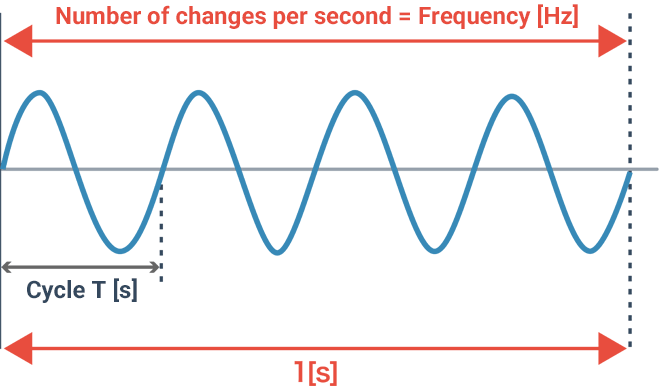
The frequency indicates how many vibrations have occurred (how many pulse signals have been output) in one second and is expressed in the unit called “hertz (Hz).” Meanwhile, the time taken for a round-trip of a pulse signal is called the “cycle.” There is a reciprocal relationship between frequency and cycle, therefore once one of them is known, the other can be obtained as a numeric value through calculation.
- Formula for frequency and cycle
- f = 1/T
Frequency f [Hz], cycle T [s]
In general, the frequency is measured for a high frequency, and the cycle is measured for a low frequency. Additionally, the method to measure pulses generated in a certain period of time is called the “direct method,” while the method to measure the cycle to obtain the frequency is called the “reciprocal method.”
Settings in terms of pulse measurement
Basic items essential for pulse measurement—including sampling cycle, input frequency band, and measurable elements—are explained below.
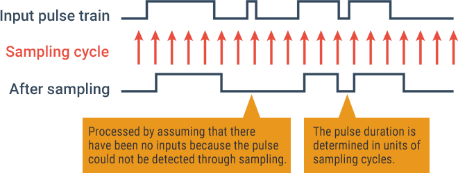
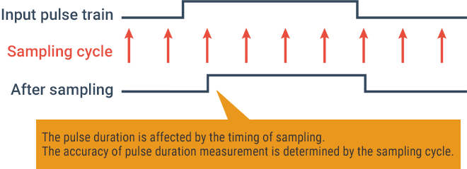
Sampling cycle
The sampling rate for pulse measurement is called the sampling cycle, and “S/s” (samples per second) is used as its unit. Because a shorter sampling cycle means a narrower sampling interval, the shorter the cycle, the more accurately the waveforms can be reproduced. A long sampling cycle raises problems such as the inability to detect short-cycle pulses and the inability to measure an accurate pulse duration. Therefore, it is important to set the optimal sampling cycle and select the optimal instrument.
Input frequency band
The input frequency band described as “DC to XX MHz” indicates the upper limit frequency where the frequency characteristics may be attenuated to 3 dB at XX MHz. Because this band affects the pulse rising time, select an instrumentation unit by taking measurement accuracy and other factors into consideration.
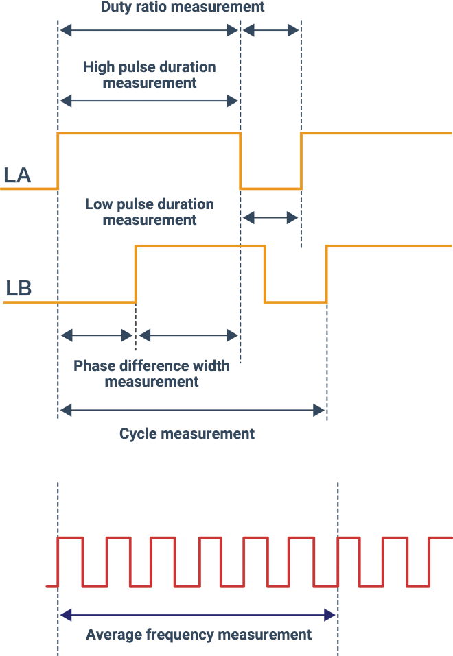
Measurable elements
In addition to the frequency and cycle of input pulses, there are other important elements such as the pulse duration (high/low), duty ratio, and phase difference width. When selecting an instrumentation unit, consider measurable elements—such as the frequency, cycle, and pulse duration—according to your required data.
In addition, there are other various elements like the pulse input type, the number of channels, the resolution, the minimum pulse duration, the measurement range, and the pulse count measurable range. For example, if you want to compare multiple pulses, you need an instrumentation unit equipped with an appropriate number of channels for that comparison.

