CAN Measurement Glossary
This section gives an easy-to-understand explanation of terms you should know to effectively utilize CAN—a serial communication protocol used in a wide variety of fields, not only in automobiles, but also in industrial machines, factory automation (FA), railways, and ships.
CAN signal
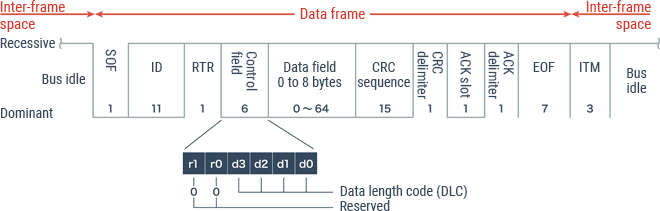
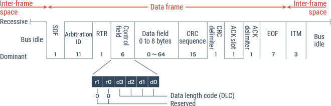
CAN signals, also called “channels,” refer to each piece of data contained in one frame. Because the data field in the standard format has a maximum size of 8 bytes, up to 64 channels of CAN signals are contained in a single data frame.

CAN bus communication
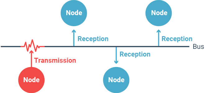
In terms of CAN, communication lines are called “buses” and control units such as ECUs (electronic control units) are called “nodes.” Because data is transmitted from nodes to other nodes via a bus, this communication is called “CAN bus communication.” Additionally, data transmission to a bus is called “bus access.” Various methods—such as “star topology,” “line topology,” and “ring topology”—are used to realize a network by connecting several nodes. CAN uses a line topology. A network can be built simply by connecting nodes, which is a simple design feature of CAN.
Communication speed
This speed indicates how many bits of data can be transmitted per second, and “bps (bits per second)” is used as its unit. For example, if 2 bits of data can be transmitted per second, the transmission speed is 2 bps. The greater this value, the more data the network can transmit per unit time. In CAN communication, the amount of data that can be transmitted at a time is limited to 8 bytes, and the maximum communication speed is 1 Mbps for high-speed CAN, or 125 kbps for low-speed CAN.
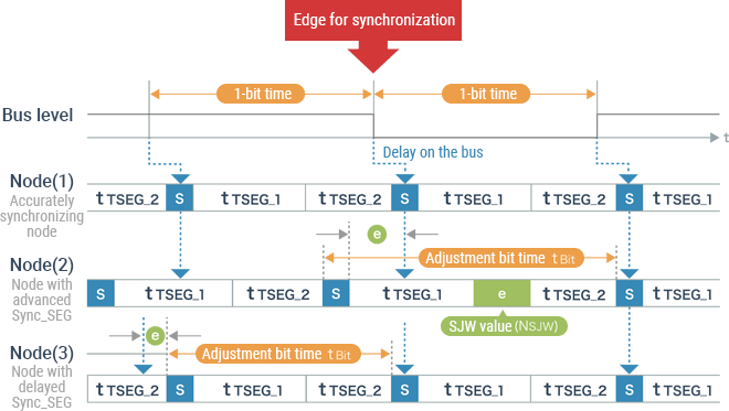
Synchronization
Each CAN communication node has a crystal oscillator in it, which determines the system clock (processing time) of its program. However, a time difference may occur between the system clock of each node due to reasons such as the power ON timing and the temperature. In CAN communication, changing the length by 1 bit disables normal communication. To prevent this problem, “synchronization” plays an important role to correct this difference in the system clocks of respective nodes.
Arbitration ID
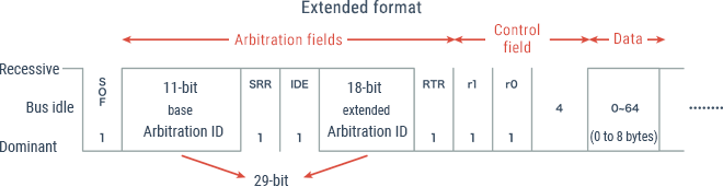
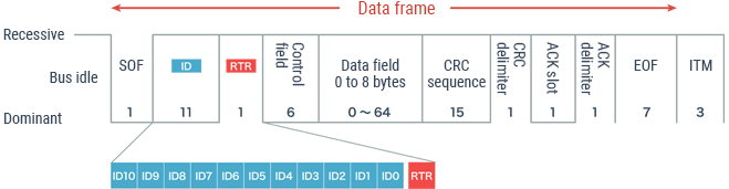
The ID that follows the “SOF” in a data frame is called the “arbitration ID.” The ID in a data frame consists of 11 bits in standard format and 29 bits (11 bits + 18 bits) in extended format. This ID is used to identify the message and determine the priority.
Arbitration
The “CSMA/CA” communication method adopted by CAN is designed to prevent data transmission from other nodes while a bus is being used by a node. In reality, however, several nodes sometimes transmit data simultaneously. The work to determine the priority in this case is called “arbitration.” Arbitration gives priority to smaller ID values. Then, if a data frame and a remote frame having the same ID are transmitted simultaneously, the RTR is additionally used for judgment, and priority is given to the data frame.
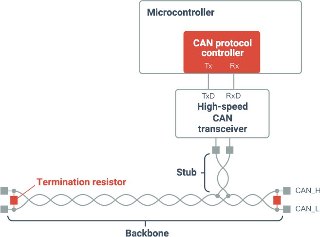
Microcontroller/CAN protocol controller/CAN transceiver
These are the pieces of hardware that physically enable CAN communication. A microcontroller is connected to a bus via a CAN transceiver. A microcontroller, which corresponds to a node that handles the processing of CAN transmitted/received data, etc., has a built-in “CAN protocol controller” that performs CAN protocol functions such as bit stuffing, arbitration, and CRC checking.