
Servo System
SV3 series
Specs Servo System SV3 series
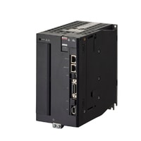
Servo amplifier (50 to 750 W)
|
Model |
SV3-005L2 |
SV3-010L2 |
SV3-020L2 |
SV3-040L2 |
SV3-075L2 |
|||
|
Image |
|
|
|
|
|
|||
|
General specifications |
Capacity |
50 W |
100 W |
200 W |
400 W |
750 W |
||
|
Input power supply |
Voltage/frequency |
Main circuit |
3-phase (or single-phase*1) 200 to 240 VAC (-15%/+10%), 50/60 Hz, 270 to 324 VDC*2 |
|||||
|
Control circuit |
Single-phase 200 to 240 VAC (-15%/+10%), 50/60 Hz, 270 to 324 VDC*2 |
|||||||
|
Allowable frequency fluctuation |
Main circuit/control circuit |
±5% max. |
||||||
|
Overvoltage category |
III |
|||||||
|
Control mode |
Three-phase full-wave rectification, IGBT, PWM control, Sine wave current drive system |
|||||||
|
Feedback |
Serial encoder (absolute) communication, Fully closed control serial communication, Analog feedback |
|||||||
|
Operating environment |
Operating atmosphere |
Enclosure rating |
IP20:SV3-005L2/010L2/020L2/040L2/075L2/100L2/150L2 |
|||||
|
Pollution degree |
2 (in an IP54 or higher control panel) However, the product must be used in the following environments: |
|||||||
|
Operating ambient temperature |
-5 to +60°C 23 to 140°F (No freezing) (reduced ratings at +55°C 131°F or higher) |
|||||||
|
Storage ambient temperature |
-20 to +85°C -4 to +185°F (No freezing) |
|||||||
|
Operating/storage ambient temperature |
95% RH or less (No condensation) |
|||||||
|
Altitude |
No more than 2,000 m 6,561.7' above sea level (reduced ratings at 1,000 m 3,280.8' or higher) |
|||||||
|
Vibration resistance |
4.9 m/s2 16.1 ft/s2 (Compliant with JIS C60068-2-6) |
|||||||
|
Impact resistance |
19.6 m/s2 64.3 ft/s2 (Compliant with JIS C60068-2-27) |
|||||||
|
Other |
No static noise, strong electric or magnetic fields, or radiation |
|||||||
|
Applied standard |
UL/CSA standards |
UL 61800-5-1, CSA 22.2 No. 274 |
||||||
|
CE marking |
Machinery Directive |
EN 61800-5-1, EN 61800-5-2, EN ISO 13849-1:2015 Cat. 3 PLe, EN IEC 62061 Maximum SIL3 |
||||||
|
EMI |
EN55011 Class A, EN61800-3, EN61000-6-4 |
|||||||
|
EMS |
EN61800-3, EN61000-6-2 |
|||||||
|
North America EMI standard |
FCC Part 15 B, ICES-003. Class A |
|||||||
|
Structure |
Type |
Base mount installation |
||||||
|
Safety function |
Safety function |
STO function (STO/EN 61800-5-2) |
||||||
|
Safety parameters |
SIL 3 / EN 61508, Maximum SIL 3 / EN IEC 62061, PLe (Category 3) / EN ISO 13849-1:2015 |
|||||||
|
Response time |
4 ms(max) |
|||||||
|
Input |
STO1, STO2: Power module base block signals |
|||||||
|
Output |
EDM: Built-in safety circuit status monitoring (fixed output) |
|||||||
|
Protection function |
Overcurrent, overvoltage, undervoltage, overload, regenerative error, etc. |
|||||||
|
Min. insulation resistance |
500 VDC 1 MΩ or more with insulation resistance meter |
|||||||
|
Insulation withstand voltage |
1,500 VAC or more (between primary side and ground) |
|||||||
|
Weight |
Approx. 0.8 kg 28.22 oz |
Approx. 1.1 kg 2.43 lb |
Approx. 1.6 kg 3.53 lb |
|||||
|
Power supply/current capacity and power loss |
Main circuit power supply |
Three-phase 200 V/Single-phase 200 V/DC 270 V |
||||||
|
Max. applicable motor capacity |
50 W |
100 W |
200 W |
400 W |
750 W |
|||
|
Power supply capacity for 1 amplifier |
Three-phase 200 V: 0.2 kVA |
Three-phase 200 V: 0.3 kVA |
Three-phase 200 V: 0.5 kVA |
Three-phase 200 V: 1.0kVA |
Three-phase 200 V: 1.6 kVA |
|||
|
Output current |
Continuous |
0.66 Arms |
0.91 Arms |
1.6 Arms |
2.8 Arms |
5.5 Arms |
||
|
Max. |
2.1 Arms |
3.2 Arms |
5.9 Arms |
9.3 Arms |
16.9 Arms |
|||
|
Main circuit power loss |
Three-phase 200 V: 5.0 W |
Three-phase 200 V: 7.0 W |
Three-phase 200 V: 11.9 W |
Three-phase 200 V: 22.5 W |
Three-phase 200 V: 38.9 W |
|||
|
Regenerative resistor power loss |
― |
Three-phase 200 V: 15 W |
||||||
|
Control circuit power loss |
12 W |
14 W |
||||||
|
Total power loss |
Three-phase 200 V: 17.0 W |
Three-phase 200 V: 19.0 W |
Three-phase 200 V: 23.9 W |
Three-phase 200 V: 34.5 W |
Three-phase 200 V: 52.9 W |
|||
|
Rated input current |
Main circuit |
Three-phase 200 V: 0.4 Arms |
Three-phase 200 V: 0.8 Arms |
Three-phase 200 V: 1.3 Arms |
Three-phase 200 V: 2.5 Arms |
Three-phase 200 V: 4.1 Arms |
||
|
Control circuit |
0.2 Arms |
|||||||
|
Rush current |
Main circuit |
29 A *3 |
34 A *3 |
|||||
|
Control circuit |
34 A *3 |
|||||||
|
Performance specifications |
Performance |
Speed control range |
1:5000 (Under conditions where load torque is equal to or less than rated torque) |
|||||
|
Speed fluctuation rate |
At load fluctuation |
0 to 100% load variation: ±0.01% or less (at rated rotation speed) |
||||||
|
At main circuit voltage change |
Rated voltage ±10%: 0% (at rated rotation speed) |
|||||||
|
At ambient temperature change |
Ambient temperature 0 to +50°C 32 to 122°F: |
|||||||
|
Torque control accuracy (reproducibility) |
±1% |
|||||||
|
Velocity frequency response |
3.1 kHz |
|||||||
|
Dynamic brake |
Operates at main circuit power off, servo alarm, servo off, limit switch detection (LSP/LSN), and forced stop detection (FSTOP) |
|||||||
|
Regenerative resistor |
Built-in regenerative resistor: Disabled at 50 to 400 W |
|||||||
|
Display Function |
Panel function |
7-segment LED |
||||||
|
Communication status indicator LED |
EtherCAT® communication: L/A × 2 |
|||||||
|
Servo functions |
Tuning |
Auto-tuning, notch filter, vibration suppression, damping control, model tracking, friction compensation, load inertia moment ratio variation compensation, deviation reduction, low-frequency vibration suppression, etc. |
||||||
|
Monitor |
Lifespan prediction, vibration, load factor, power consumption, temperature, etc. |
|||||||
|
I/O specifications |
Sequence input signal |
Number of inputs |
7 (3 high-speed inputs, 4 general-purpose inputs) |
|||||
|
Max. input voltage |
28.8 VDC |
|||||||
|
Rated input voltage |
24 VDC |
|||||||
|
Min. ON voltage |
19 VDC |
|||||||
|
Max. OFF current/voltage |
High-speed input: 0.1 mA, General-purpose input: 0.3 mA |
|||||||
|
Common point mode |
7 points/1 common (1 terminal) (bidirectional) |
|||||||
|
Input time constant |
250 μs, 500 μs, 1 ms, 2.5 ms, 5 ms, 10 ms |
|||||||
|
Input current |
High-speed input: 4.4 mA, General-purpose input: 4.5 mA |
|||||||
|
Input impedance |
Approx. 5.1 kΩ |
|||||||
|
Assignable input signals |
All signal assignment, Logic settable forced stop (FSTOP), Probe 1 latch input (PROBE1), Probe 2 latch input (PROBE2), Home switch input (HOME), Forward side limit switch (LSP), Reverse side limit switch (LSN), Forward side torque limit selection (PTL), Reverse side torque limit selection (NTL) |
|||||||
|
Sequence output signal |
Number of outputs |
4 |
||||||
|
Output mode |
Transistor NPN output |
|||||||
|
Rated load |
30 VDC/50 mA |
|||||||
|
Leakage current when OFF |
0.5 mA |
|||||||
|
Residual voltage when ON |
1.5 VDC or less |
|||||||
|
Common point mode |
Independent common |
|||||||
|
Assignable output signals |
Assignment of each signal except ALARM signal, Logic setting available alarm (ALARM), In-position (INPOS), Velocity matching (VCMP), Zero speed detection (ZSP), Ready to run (RDY), Torque limiting (TLM), Velocity limiting (VLM), Electromagnetic brake timing (BRAKE), Warning (WARN), Near positioning (NEAR) |
|||||||
|
Analog Feedback Input signal monitor |
Max. input voltage |
±12 V |
||||||
|
Accuracy |
±1% of F.S. |
|||||||
|
Resolution |
±12 bits |
|||||||
|
Input impedance |
30 kΩ |
|||||||
|
Encoder division pulse output signal |
Output mode |
A-phase (A+/A-), B-phase B (B+/B-), Z-phase (Z+/Z-): Differential line driver output |
||||||
|
Line driver |
SN75ALS174 (T.I.) equivalent |
|||||||
|
Output frequency |
1.6 Mpps (at 2-phase quadruplication, equivalent to 6.4 MHz)*5 |
|||||||
|
Analog monitor output |
No. of channels |
2 ch |
||||||
|
Output range |
±10 V (Linearity effective range: ±8 V) |
|||||||
|
Resolution |
16 bits |
|||||||
|
Conversion precision |
±20 mV (typ.) |
|||||||
|
Max. allowable load current |
±10 mA |
|||||||
|
Conversion speed |
1.2 ms (typ.) |
|||||||
|
Communication specifications |
EtherCAT® communication |
Applicable communication standards |
IEC 61158 Type12, |
|||||
|
Physical layer |
100 BASE-TX(IEEE802.3) |
|||||||
|
Cable |
Category 5 STP, 2 pair |
|||||||
|
Mailbox |
Emergency messages, SDO requests, SDO responses |
|||||||
|
Distributed clocks |
Free-run, DC mode (switchable), Supported DC cycles (62.5 μs to 4 ms, in 62.5 μs increments) |
|||||||
|
Max. distance between stations |
50 m 164.0' |
|||||||
|
USB communication |
Connected device |
PC |
||||||
|
Communication standard |
USB 2.0–compliant |
|||||||
|
Function |
Status display, Parameter settings, Tuning, etc. |
|||||||
|
*1 Single-phase input can only be used with the SV3-005L2, SV3-010L2, SV3-020L2, SV3-040L2, and SV3-075L2. |
||||||||
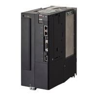
Servo amplifier (1 to 5 kW)
|
Model |
SV3-100L2 |
SV3-150L2 |
SV3-200L2 |
SV3-300L2 |
SV3-500L2 |
|||
|
Image |
|
|
|
|
|
|||
|
General specifications |
Capacity |
1.0 kW |
1.5 kW |
2.0 kW |
3.0 kW |
5.0 kW |
||
|
Input power supply |
Voltage/frequency |
Main circuit |
3-phase (or single-phase*1) 200 to 240 VAC (-15%/+10%), 50/60 Hz, 270 to 324 VDC*2 |
|||||
|
Control circuit |
Single-phase 200 to 240 VAC (-15%/+10%), 50/60 Hz, 270 to 324 VDC*2 |
|||||||
|
Allowable frequency fluctuation |
Main circuit/control circuit |
±5% max. |
||||||
|
Overvoltage category |
III |
|||||||
|
Control mode |
Three-phase full-wave rectification, IGBT, PWM control, Sine wave current drive system |
|||||||
|
Feedback |
Serial encoder (absolute) communication, Fully closed control serial communication, Analog feedback |
|||||||
|
Operating environment |
Operating atmosphere |
Enclosure rating |
IP20:SV3-005L2/010L2/020L2/040L2/075L2/100L2/150L2 |
|||||
|
Pollution degree |
2 (in an IP54 or higher control panel) However, the product must be used in the following environments: |
|||||||
|
Operating ambient temperature |
-5 to +60°C 23 to 140°F (No freezing) (reduced ratings at +55°C 131°F or higher) |
|||||||
|
Storage ambient temperature |
-20 to +85°C -4 to +185°F (No freezing) |
|||||||
|
Operating/storage ambient temperature |
95% RH or less (No condensation) |
|||||||
|
Altitude |
No more than 2,000 m 6,561.7' above sea level (reduced ratings at 1,000 m 3,280.8' or higher) |
|||||||
|
Vibration resistance |
4.9 m/s2 16.1 ft/s2 (Compliant with JIS C60068-2-6) |
|||||||
|
Impact resistance |
19.6 m/s2 64.3 ft/s2 (Compliant with JIS C60068-2-27) |
|||||||
|
Other |
No static noise, strong electric or magnetic fields, or radiation |
|||||||
|
Applied standard |
UL/CSA standards |
UL 61800-5-1, CSA 22.2 No. 274 |
||||||
|
CE marking |
Machinery Directive |
EN 61800-5-1, EN 61800-5-2, EN ISO 13849-1:2015 Cat. 3 PLe, EN IEC 62061 Maximum SIL3 |
||||||
|
EMI |
EN55011 Class A, EN61800-3, EN61000-6-4 |
|||||||
|
EMS |
EN61800-3, EN61000-6-2 |
|||||||
|
North America EMI standard |
FCC Part 15 B, ICES-003. Class A |
|||||||
|
Structure |
Type |
Base mount installation |
||||||
|
Safety function |
Safety function |
STO function (STO/EN 61800-5-2) |
||||||
|
Safety parameters |
SIL 3 / EN 61508, Maximum SIL 3 / EN IEC 62061, PLe (Category 3) / EN ISO 13849-1:2015 |
|||||||
|
Response time |
4 ms(max) |
|||||||
|
Input |
STO1, STO2: Power module base block signals |
|||||||
|
Output |
EDM: Built-in safety circuit status monitoring (fixed output) |
|||||||
|
Protection function |
Overcurrent, overvoltage, undervoltage, overload, regenerative error, etc. |
|||||||
|
Min. insulation resistance |
500 VDC 1 MΩ or more with insulation resistance meter |
|||||||
|
Insulation withstand voltage |
1,500 VAC or more (between primary side and ground) |
|||||||
|
Weight |
Approx. 1.6 kg 3.53 lb |
Approx. 2.1 kg 4.63 lb |
Approx. 2.8 kg 6.17 lb |
Approx. 4.4 kg 9.70 lb |
||||
|
Power supply/current capacity and power loss |
Main circuit power supply |
Three-phase 200 V/DC 270 V |
||||||
|
Max. applicable motor capacity |
1.0 kW |
1.5 kW |
2.0 kW |
3.0 kW |
5.0 kW |
|||
|
Power supply capacity for 1 amplifier |
2.3 kVA |
3.2 kVA |
4.0 kVA |
5.9 kVA |
7.5 kVA |
|||
|
Output current |
Continuous |
7.6 Arms |
11.6 Arms |
18.5 Arms |
19.6 Arms |
32.9 Arms |
||
|
Max. |
17 Arms |
28 Arms |
42 Arms |
56 Arms |
84 Arms |
|||
|
Main circuit power loss |
Three-phase 200 V: 49.2 W |
Three-phase 200 V: 72.6 W |
Three-phase 200 V: 104.2 W |
Three-phase 200 V: 114.2 W |
Three-phase 200 V: 226.6 W |
|||
|
Regenerative resistor power loss |
Three-phase 200 V: 15 W |
Three-phase 200 V: 30 W |
Three-phase 200 V: 36 W |
|||||
|
Control circuit power loss |
14 W |
15 W |
16 W |
19 W |
||||
|
Total power loss |
Three-phase 200 V: 63.2 W |
Three-phase 200 V: 87.6 W |
Three-phase 200 V: 120.2 W |
Three-phase 200 V: 130.2 W |
Three-phase 200 V: 245.6 W |
|||
|
Rated input current |
Main circuit |
Three-phase 200 V: 5.7 Arms |
Three-phase 200 V: 7.3 Arms |
Three-phase 200 V: 10 Arms |
Three-phase 200 V: 15 Arms |
Three-phase 200 V: 25 Arms |
||
|
Control circuit |
0.2 Arms |
0.25 Arms |
0.3 Arms |
|||||
|
Rush current |
Main circuit |
34 A *3 |
Three-phase 200 V: 68 A *3 |
|||||
|
Control circuit |
34 A *3 |
|||||||
|
Performance specifications |
Performance |
Speed control range |
1:5000 (Under conditions where load torque is equal to or less than rated torque) |
|||||
|
Speed fluctuation rate |
At load fluctuation |
0 to 100% load variation: ±0.01% or less (at rated rotation speed) |
||||||
|
At main circuit voltage change |
Rated voltage ±10%: 0% (at rated rotation speed) |
|||||||
|
At ambient temperature change |
Ambient temperature 0 to +50°C 32 to 122°F: |
|||||||
|
Torque control accuracy (reproducibility) |
±1% |
|||||||
|
Velocity frequency response |
3.1 kHz |
|||||||
|
Dynamic brake |
Operates at main circuit power off, servo alarm, servo off, limit switch detection (LSP/LSN), and forced stop detection (FSTOP) |
|||||||
|
Regenerative resistor |
Built-in regenerative resistor: Disabled at 50 to 400 W |
|||||||
|
Display Function |
Panel function |
7-segment LED |
||||||
|
Communication status indicator LED |
EtherCAT® communication: L/A × 2 |
|||||||
|
Servo functions |
Tuning |
Auto-tuning, notch filter, vibration suppression, damping control, model tracking, friction compensation, load inertia moment ratio variation compensation, deviation reduction, low-frequency vibration suppression, etc. |
||||||
|
Monitor |
Lifespan prediction, vibration, load factor, power consumption, temperature, etc. |
|||||||
|
I/O specifications |
Sequence input signal |
Number of inputs |
7 (3 high-speed inputs, 4 general-purpose inputs) |
|||||
|
Max. input voltage |
28.8 VDC |
|||||||
|
Rated input voltage |
24 VDC |
|||||||
|
Min. ON voltage |
19 VDC |
|||||||
|
Max. OFF current/voltage |
High-speed input: 0.1 mA, General-purpose input: 0.3 mA |
|||||||
|
Common point mode |
7 points/1 common (1 terminal) (bidirectional) |
|||||||
|
Input time constant |
250 μs, 500 μs, 1 ms, 2.5 ms, 5 ms, 10 ms |
|||||||
|
Input current |
High-speed input: 4.4 mA, General-purpose input: 4.5 mA |
|||||||
|
Input impedance |
Approx. 5.1 kΩ |
|||||||
|
Assignable input signals |
All signal assignment, Logic settable forced stop (FSTOP), Probe 1 latch input (PROBE1), Probe 2 latch input (PROBE2), Home switch input (HOME), Forward side limit switch (LSP), Reverse side limit switch (LSN), Forward side torque limit selection (PTL), Reverse side torque limit selection (NTL) |
|||||||
|
Sequence output signal |
Number of outputs |
4 |
||||||
|
Output mode |
Transistor NPN output |
|||||||
|
Rated load |
30 VDC/50 mA |
|||||||
|
Leakage current when OFF |
0.5 mA |
|||||||
|
Residual voltage when ON |
1.5 VDC or less |
|||||||
|
Common point mode |
Independent common |
|||||||
|
Assignable output signals |
Assignment of each signal except ALARM signal, Logic setting available alarm (ALARM), In-position (INPOS), Velocity matching (VCMP), Zero speed detection (ZSP), Ready to run (RDY), Torque limiting (TLM), Velocity limiting (VLM), Electromagnetic brake timing (BRAKE), Warning (WARN), Near positioning (NEAR) |
|||||||
|
Analog Feedback Input signal monitor |
Max. input voltage |
±12 V |
||||||
|
Accuracy |
±1% of F.S. |
|||||||
|
Resolution |
±12 bits |
|||||||
|
Input impedance |
30 kΩ |
|||||||
|
Encoder division pulse output signal |
Output mode |
A-phase (A+/A-), B-phase B (B+/B-), Z-phase (Z+/Z-): Differential line driver output |
||||||
|
Line driver |
SN75ALS174 (T.I.) equivalent |
|||||||
|
Output frequency |
1.6 Mpps (at 2-phase quadruplication, equivalent to 6.4 MHz)*5 |
|||||||
|
Analog monitor output |
No. of channels |
2 ch |
||||||
|
Output range |
±10 V (Linearity effective range: ±8 V) |
|||||||
|
Resolution |
16 bits |
|||||||
|
Conversion precision |
±20 mV (typ.) |
|||||||
|
Max. allowable load current |
±10 mA |
|||||||
|
Conversion speed |
1.2 ms (typ.) |
|||||||
|
Communication specifications |
EtherCAT® communication |
Applicable communication standards |
IEC 61158 Type12, |
|||||
|
Physical layer |
100 BASE-TX(IEEE802.3) |
|||||||
|
Cable |
Category 5 STP, 2 pair |
|||||||
|
Mailbox |
Emergency messages, SDO requests, SDO responses |
|||||||
|
Distributed clocks |
Free-run, DC mode (switchable), Supported DC cycles (62.5 μs to 4 ms, in 62.5 μs increments) |
|||||||
|
Max. distance between stations |
50 m 164.0' |
|||||||
|
USB communication |
Connected device |
PC |
||||||
|
Communication standard |
USB 2.0–compliant |
|||||||
|
Function |
Status display, Parameter settings, Tuning, etc. |
|||||||
|
*1 Single-phase input can only be used with the SV3-005L2, SV3-010L2, SV3-020L2, SV3-040L2, and SV3-075L2. |
||||||||
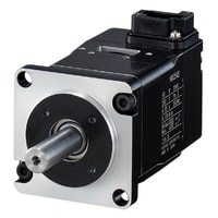
Servo motor Standard motor: Splined axis
|
Model |
SV3-M005AK |
SV3-M010AK |
SV3-M020AK |
SV3-M040AK |
SV3-M075AK |
|||
|
Image |
|
|
|
|
|
|||
|
General specifications |
Applicable servo amplifier |
SV3-005L2 |
SV3-010L2 |
SV3-020L2 |
SV3-040L2 |
SV3-075L2 |
||
|
Rated output |
50 W |
100 W |
200 W |
400 W |
750 W |
|||
|
Rated torque |
0.159 N·m *1 |
0.318 N·m *1 |
0.637 N·m *1 |
1.27 N·m *1 |
2.39 N·m *1 |
|||
|
Instant maximum torque |
0.557 N·m |
1.11 N·m |
2.23 N·m |
4.46 N·m |
8.36 N·m |
|||
|
Rated current |
0.55 Arms |
0.85 Arms |
1.6 Arms |
2.5 Arms |
4.4 Arms |
|||
|
Instant maximum current |
2.0 Arms |
3.1 Arms |
5.8 Arms |
9.3 Arms |
16.9 Arms |
|||
|
Rated rotation speed |
3,000 min-1 |
|||||||
|
High rotation speed |
7,000 min-1 |
|||||||
|
Torque constant |
0.316 N·m/Arms |
0.413 N·m/Arms |
0.444 N·m/Arms |
0.544 N·m/Arms |
0.584 N·m/Arms |
|||
|
Rotor moment of inertia |
0.0457 ×10⁻⁴ kg·m2 |
0.0705 ×10⁻⁴ kg·m2 |
0.267 ×10⁻⁴ kg·m2 |
0.490 ×10⁻⁴ kg·m2 |
1.59 ×10⁻⁴ kg·m2 |
|||
|
Rated power rating |
5.53 kW/s |
14.3 kW/s |
15.1 kW/s |
32.9 kW/s |
35.9 kW/s |
|||
|
Rated angle acceleration |
34,700 rad/s2 |
45,100 rad/s2 |
23,800 rad/s2 |
25,900 rad/s2 |
15,000 rad/s2 |
|||
|
Excitation method |
Permanent magnet |
|||||||
|
Position/speed detection encoder |
Resolution |
26 bit |
||||||
|
Type |
Absolute (ABS) type |
|||||||
|
Operating environment |
Enclosure rating |
Completely closed, self-cooling, IP67 standard (excluding connector and axis through-hole) |
||||||
|
Operating ambient temperature |
0 to +60°C 32 to 140°F (reduced ratings at +40°C 104°F or higher) |
|||||||
|
Storage ambient temperature |
-20 to +60°C -4 to +140°F |
|||||||
|
Operating/storage ambient temperature |
20% to 80% RH (No condensation) |
|||||||
|
Operating atmosphere |
Indoors (No corrosive gas, flammable gas, oil mist, or dust) |
|||||||
|
Altitude |
2,000 m 6,561.7' or less (reduced ratings at 1,000 m 3,280.8' or more) |
|||||||
|
Vibration rank |
V15 |
|||||||
|
Vibration resistance |
49 m/s2 160.8 ft/s2 with servo motor flange surface as reference |
|||||||
|
Impact resistance |
490 m/s2 1,607.6 ft/s2 with servo motor flange surface as reference, 2 times |
|||||||
|
Isolation rank |
UL: Class A, CE: Class B |
|||||||
|
Min. insulation resistance |
500 VDC 10 MΩ or more with insulation resistance meter |
|||||||
|
Isolation voltage tolerance |
1,500 VAC for 1 minute |
|||||||
|
Approved standards |
UL/CSA standards |
UL1004-1, UL1004-6, CSA C22.2 No.100 |
||||||
|
CE marking |
Low-voltage directive |
EN60034-1, EN60034-5 |
||||||
|
EMI |
EN55011 Class A, EN61800-3, EN61000-6-4 |
|||||||
|
EMS |
EN61800-3, EN61000-6-2 |
|||||||
|
North America EMI standard |
FCC Part 15 B, ICES-003. Class A |
|||||||
|
Allowable load inertia moment |
35× |
15×*2 |
10×*2 |
12×*2 |
||||
|
Approx. weight |
0.3 kg 10.58 oz |
0.4 kg 14.11 oz |
0.8 kg 28.22 oz |
1.1 kg 2.43 lb |
2.2 kg 4.85 lb |
|||
|
*1 50 W to 750 W rated torque is continuously allowable with an ambient temperature of 40°C 104°F and 200 × 200 × 6 mm 7.87" × 7.87" × 0.24" (50 W/100 W) or 250 × 250 × 6 mm 9.84" × 9.84" × 0.24" (200 W to 750 W) mountable aluminum heat sink. |
||||||||
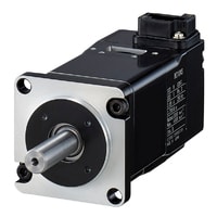
Servo motor Standard motor: Straight axis
|
Model |
SV3-M005AS |
SV3-M010AS |
SV3-M020AS |
SV3-M040AS |
SV3-M075AS |
|||
|
Image |
|
|
|
|
|
|||
|
General specifications |
Applicable servo amplifier |
SV3-005L2 |
SV3-010L2 |
SV3-020L2 |
SV3-040L2 |
SV3-075L2 |
||
|
Rated output |
50 W |
100 W |
200 W |
400 W |
750 W |
|||
|
Rated torque |
0.159 N·m *1 |
0.318 N·m *1 |
0.637 N·m *1 |
1.27 N·m *1 |
2.39 N·m *1 |
|||
|
Instant maximum torque |
0.557 N·m |
1.11 N·m |
2.23 N·m |
4.46 N·m |
8.36 N·m |
|||
|
Rated current |
0.55 Arms |
0.85 Arms |
1.6 Arms |
2.5 Arms |
4.4 Arms |
|||
|
Instant maximum current |
2.0 Arms |
3.1 Arms |
5.8 Arms |
9.3 Arms |
16.9 Arms |
|||
|
Rated rotation speed |
3,000 min-1 |
|||||||
|
High rotation speed |
7,000 min-1 |
|||||||
|
Torque constant |
0.316 N·m/Arms |
0.413 N·m/Arms |
0.444 N·m/Arms |
0.544 N·m/Arms |
0.584 N·m/Arms |
|||
|
Rotor moment of inertia |
0.0457 ×10⁻⁴ kg·m2 |
0.0705 ×10⁻⁴ kg·m2 |
0.267 ×10⁻⁴ kg·m2 |
0.490 ×10⁻⁴ kg·m2 |
1.59 ×10⁻⁴ kg·m2 |
|||
|
Rated power rating |
5.53 kW/s |
14.3 kW/s |
15.1 kW/s |
32.9 kW/s |
35.9 kW/s |
|||
|
Rated angle acceleration |
34,700 rad/s2 |
45,100 rad/s2 |
23,800 rad/s2 |
25,900 rad/s2 |
15,000 rad/s2 |
|||
|
Excitation method |
Permanent magnet |
|||||||
|
Position/speed detection encoder |
Resolution |
26 bit |
||||||
|
Type |
Absolute (ABS) type |
|||||||
|
Operating environment |
Enclosure rating |
Completely closed, self-cooling, IP67 standard (excluding connector and axis through-hole) |
||||||
|
Operating ambient temperature |
0 to +60°C 32 to 140°F (reduced ratings at +40°C 104°F or higher) |
|||||||
|
Storage ambient temperature |
-20 to +60°C -4 to +140°F |
|||||||
|
Operating/storage ambient temperature |
20% to 80% RH (No condensation) |
|||||||
|
Operating atmosphere |
Indoors (No corrosive gas, flammable gas, oil mist, or dust) |
|||||||
|
Altitude |
2,000 m 6,561.7' or less (reduced ratings at 1,000 m 3,280.8' or more) |
|||||||
|
Vibration rank |
V15 |
|||||||
|
Vibration resistance |
49 m/s2 160.8 ft/s2 with servo motor flange surface as reference |
|||||||
|
Impact resistance |
490 m/s2 1,607.6 ft/s2 with servo motor flange surface as reference, 2 times |
|||||||
|
Isolation rank |
UL: Class A, CE: Class B |
|||||||
|
Min. insulation resistance |
500 VDC 10 MΩ or more with insulation resistance meter |
|||||||
|
Isolation voltage tolerance |
1,500 VAC for 1 minute |
|||||||
|
Approved standards |
UL/CSA standards |
UL1004-1, UL1004-6, CSA C22.2 No.100 |
||||||
|
CE marking |
Low-voltage directive |
EN60034-1, EN60034-5 |
||||||
|
EMI |
EN55011 Class A, EN61800-3, EN61000-6-4 |
|||||||
|
EMS |
EN61800-3, EN61000-6-2 |
|||||||
|
North America EMI standard |
FCC Part 15 B, ICES-003. Class A |
|||||||
|
Allowable load inertia moment |
35× |
15×*2 |
10×*2 |
12×*2 |
||||
|
Approx. weight |
0.3 kg 10.58 oz |
0.4 kg 14.11 oz |
0.8 kg 28.22 oz |
1.1 kg 2.43 lb |
2.2 kg 4.85 lb |
|||
|
*1 50 W to 750 W rated torque is continuously allowable with an ambient temperature of 40°C 104°F and 200 × 200 × 6 mm 7.87" × 7.87" × 0.24" (50 W/100 W) or 250 × 250 × 6 mm 9.84" × 9.84" × 0.24" (200 W to 750 W) mountable aluminum heat sink. |
||||||||
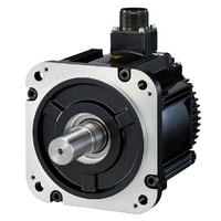
Servo motor Standard motor: Straight axis
|
Model |
SV3-M100AS |
SV3-M150AS |
SV3-M200AS |
SV3-M300AS |
SV3-M500AS |
|||
|
Image |
|
|
|
|
|
|||
|
General specifications |
Applicable servo amplifier |
SV3-100L2 |
SV3-150L2 |
SV3-200L2 |
SV3-300L2, SV3-500L2 |
SV3-500L2 |
||
|
Rated output |
0.85k W |
1.3k W |
1.8k W |
SV3-300L2: 2.4k W |
4.4k W |
|||
|
Rated torque |
5.39 N·m *1 |
8.34 N·m *1 |
11.5 N·m *1 |
SV3-300L2: 15.1 N·m |
28.4 N·m *1 |
|||
|
Instant maximum torque |
14.2 N·m |
23.3 N·m |
28.7 N·m |
SV3-300L2: 45.1 N·m |
71.6 N·m |
|||
|
Rated current |
6.9 Arms |
10.7 Arms |
16.7 Arms |
SV3-300L2: 19.6 Arms |
32.8 Arms |
|||
|
Instant maximum current |
17 Arms |
28 Arms |
42 Arms |
SV3-300L2: 56 Arms |
84 Arms |
|||
|
Rated rotation speed |
1,500 min-1 |
|||||||
|
High rotation speed |
4,000 min-1 |
|||||||
|
Torque constant |
0.859 N·m/Arms |
0.891 N·m/Arms |
0.748 N·m/Arms |
0.826 N·m/Arms |
0.932 N·m/Arms |
|||
|
Rotor moment of inertia |
13.9 ×10⁻⁴ kg·m2 |
19.9 ×10⁻⁴ kg·m2 |
26.0 ×10⁻⁴ kg·m2 |
46.0 ×10⁻⁴ kg·m2 |
67.5 ×10⁻⁴ kg·m2 |
|||
|
Rated power rating |
20.9 kW/s |
35.0 kW/s |
50.9 kW/s |
SV3-300L2: 49.5 kW/s |
119 kW/s |
|||
|
Rated angle acceleration |
3,880 rad/s2 |
4,190 rad/s2 |
4,420 rad/s2 |
SV3-300L2: 3,280 rad/s2 |
4,210 rad/s2 |
|||
|
Excitation method |
Permanent magnet |
|||||||
|
Position/speed detection encoder |
Resolution |
26 bit |
||||||
|
Type |
Absolute (ABS) type |
|||||||
|
Operating environment |
Enclosure rating |
Completely closed, self-cooling, IP67 standard (excluding connector and axis through-hole) |
||||||
|
Operating ambient temperature |
0 to +60°C 32 to 140°F (reduced ratings at +40°C 104°F or higher) |
|||||||
|
Storage ambient temperature |
-20 to +60°C -4 to +140°F |
|||||||
|
Operating/storage ambient temperature |
20% to 80% RH (No condensation) |
|||||||
|
Operating atmosphere |
Indoors (No corrosive gas, flammable gas, oil mist, or dust) |
|||||||
|
Altitude |
2,000 m 6,561.7' or less (reduced ratings at 1,000 m 3,280.8' or more) |
|||||||
|
Vibration rank |
V15 |
|||||||
|
Vibration resistance |
49 m/s2 160.8 ft/s2 with servo motor flange surface as reference (up/down, left/right) |
|||||||
|
Impact resistance |
490 m/s2 1,607.6 ft/s2 with servo motor flange surface as reference, 2 times |
|||||||
|
Isolation rank |
Class F |
|||||||
|
Min. insulation resistance |
500 VDC 10 MΩ or more with insulation resistance meter |
|||||||
|
Isolation voltage tolerance |
1,500 VAC for 1 minute |
|||||||
|
Approved standards |
UL/CSA standards |
UL1004-1, UL1004-6, CSA C22.2 No.100 |
||||||
|
CE marking |
Low-voltage directive |
EN60034-1, EN60034-5 |
||||||
|
EMI |
EN55011 Class A, EN61800-3, EN61000-6-4 |
|||||||
|
EMS |
EN61800-3, EN61000-6-2 |
|||||||
|
North America EMI standard |
FCC Part 15 B, ICES-003. Class A |
|||||||
|
Allowable load inertia moment |
5×*2 |
5× |
SV3-300L2: 3× |
5×*2 |
||||
|
Approx. weight |
5.5 kg 12.13 lb |
7.1 kg 15.65 lb |
8.6 kg 18.96 lb |
13.5 kg 29.76 lb |
17.5 kg 38.58 lb |
|||
|
*1 50 W to 750 W rated torque is continuously allowable with an ambient temperature of 40°C 104°F and 200 × 200 × 6 mm 7.87" × 7.87" × 0.24" (50 W/100 W) or 250 × 250 × 6 mm 9.84" × 9.84" × 0.24" (200 W to 750 W) mountable aluminum heat sink. |
||||||||
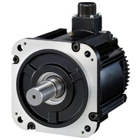
Servo motor Motor with electromagnetic brake: Splined axis
|
Model |
SV3-B005AK *1 |
SV3-B010AK *1 |
SV3-B020AK *1 |
SV3-B040AK *1 |
SV3-B075AK *1 |
|||
|
Image |
|
|
|
|
|
|||
|
General specifications |
Applicable servo amplifier |
SV3-005L2 |
SV3-010L2 |
SV3-020L2 |
SV3-040L2 |
SV3-075L2 |
||
|
Rated output |
50 W |
100 W |
200 W |
400 W |
750 W |
|||
|
Rated torque |
0.159 N·m *2 |
0.318 N·m *2 |
0.637 N·m *2 |
1.27 N·m *2 |
2.39 N·m *2 |
|||
|
Instant maximum torque |
0.557 N·m |
1.11 N·m |
2.23 N·m |
4.46 N·m |
8.36 N·m |
|||
|
Rated current |
0.55 Arms |
0.85 Arms |
1.6 Arms |
2.5 Arms |
4.4 Arms |
|||
|
Instant maximum current |
2.0 Arms |
3.1 Arms |
5.8 Arms |
9.3 Arms |
16.9 Arms |
|||
|
Rated rotation speed |
3,000 min-1 |
|||||||
|
High rotation speed |
7,000 min-1 |
|||||||
|
Torque constant |
0.316 N·m/Arms |
0.413 N·m/Arms |
0.444 N·m/Arms |
0.544 N·m/Arms |
0.584 N·m/Arms |
|||
|
Rotor moment of inertia |
0.0537 ×10⁻⁴ kg·m2 |
0.0785 ×10⁻⁴ kg·m2 |
0.327 ×10⁻⁴ kg·m2 |
0.550 ×10⁻⁴ kg·m2 |
1.76 ×10⁻⁴ kg·m2 |
|||
|
Rated power rating |
4.70 kW/s |
12.8 kW/s |
12.4 kW/s |
29.3 kW/s |
32.4 kW/s |
|||
|
Rated angle acceleration |
29,600 rad/s2 |
40,500 rad/s2 |
19,400 rad/s2 |
23,000 rad/s2 |
13,500 rad/s2 |
|||
|
Excitation method |
Permanent magnet |
|||||||
|
Position/speed detection encoder |
Resolution |
26 bit |
||||||
|
Type |
Absolute (ABS) type |
|||||||
|
Operating environment |
Enclosure rating |
Completely closed, self-cooling, IP67 standard (excluding connector and axis through-hole) |
||||||
|
Operating ambient temperature |
0 to +60°C 32 to 140°F (reduced ratings at +40°C 104°F or higher) |
|||||||
|
Storage ambient temperature |
-20 to +60°C -4 to +140°F |
|||||||
|
Operating/storage ambient temperature |
20% to 80% RH (No condensation) |
|||||||
|
Operating atmosphere |
Indoors (No corrosive gas, flammable gas, oil mist, or dust) |
|||||||
|
Altitude |
2,000 m 6,561.7' or less (reduced ratings at 1,000 m 3,280.8' or more) |
|||||||
|
Vibration rank |
V15 |
|||||||
|
Vibration resistance |
49 m/s2 160.8 ft/s2 with servo motor flange surface as reference |
|||||||
|
Impact resistance |
490 m/s2 1,607.6 ft/s2 with servo motor flange surface as reference, 2 times |
|||||||
|
Isolation rank |
UL: Class A, CE: Class B |
|||||||
|
Min. insulation resistance |
500 VDC 10 MΩ or more with insulation resistance meter |
|||||||
|
Isolation voltage tolerance |
1,500 VAC for 1 minute |
|||||||
|
Approved standards |
UL/CSA standards |
UL1004-1, UL1004-6, CSA C22.2 No.100 |
||||||
|
CE marking |
Low-voltage directive |
EN60034-1, EN60034-5 |
||||||
|
EMI |
EN55011 Class A, EN61800-3, EN61000-6-4 |
|||||||
|
EMS |
EN61800-3, EN61000-6-2 |
|||||||
|
North America EMI standard |
FCC Part 15 B, ICES-003. Class A |
|||||||
|
Allowable load inertia moment |
35× |
15×*3 |
10×*3 |
12×*3 |
||||
|
Approx. weight |
0.6 kg 21.16 oz |
0.7 kg 24.69 oz |
1.4 kg 3.09 lb |
1.7 kg 3.75 lb |
2.8 kg 6.17 lb |
|||
|
Electromagnetic brake specifications |
Capacity |
5.5 W |
6 W |
6.5 W |
||||
|
Rated voltage |
24 VDC ±10% |
|||||||
|
Rated current (@20°C 68°F) |
0.23 A |
0.25 A |
0.27 A |
|||||
|
Holding torque |
0.159 N·m |
0.318 N·m |
0.637 N·m |
1.27 N·m |
2.39 N·m |
|||
|
Release time |
60 ms |
80 ms |
||||||
|
Operating time |
100 ms |
|||||||
|
*1 The open and operation times of the electromagnetic brake depend on the discharge circuit. |
||||||||
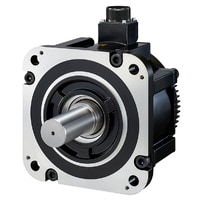
Servo motor Motor with electromagnetic brake: Straight axis
|
Model |
SV3-B005AS *1 |
SV3-B010AS *1 |
SV3-B020AS *1 |
SV3-B040AS *1 |
SV3-B075AS *1 |
|||
|
Image |
|
|
|
|
|
|||
|
General specifications |
Applicable servo amplifier |
SV3-005L2 |
SV3-010L2 |
SV3-020L2 |
SV3-040L2 |
SV3-075L2 |
||
|
Rated output |
50 W |
100 W |
200 W |
400 W |
750 W |
|||
|
Rated torque |
0.159 N·m *2 |
0.318 N·m *2 |
0.637 N·m *2 |
1.27 N·m *2 |
2.39 N·m *2 |
|||
|
Instant maximum torque |
0.557 N·m |
1.11 N·m |
2.23 N·m |
4.46 N·m |
8.36 N·m |
|||
|
Rated current |
0.55 Arms |
0.85 Arms |
1.6 Arms |
2.5 Arms |
4.4 Arms |
|||
|
Instant maximum current |
2.0 Arms |
3.1 Arms |
5.8 Arms |
9.3 Arms |
16.9 Arms |
|||
|
Rated rotation speed |
3,000 min-1 |
|||||||
|
High rotation speed |
7,000 min-1 |
|||||||
|
Torque constant |
0.316 N·m/Arms |
0.413 N·m/Arms |
0.444 N·m/Arms |
0.544 N·m/Arms |
0.584 N·m/Arms |
|||
|
Rotor moment of inertia |
0.0537 ×10⁻⁴ kg·m2 |
0.0785 ×10⁻⁴ kg·m2 |
0.327 ×10⁻⁴ kg·m2 |
0.550 ×10⁻⁴ kg·m2 |
1.76 ×10⁻⁴ kg·m2 |
|||
|
Rated power rating |
4.70 kW/s |
12.8 kW/s |
12.4 kW/s |
29.3 kW/s |
32.4 kW/s |
|||
|
Rated angle acceleration |
29,600 rad/s2 |
40,500 rad/s2 |
19,400 rad/s2 |
23,000 rad/s2 |
13,500 rad/s2 |
|||
|
Excitation method |
Permanent magnet |
|||||||
|
Position/speed detection encoder |
Resolution |
26 bit |
||||||
|
Type |
Absolute (ABS) type |
|||||||
|
Operating environment |
Enclosure rating |
Completely closed, self-cooling, IP67 standard (excluding connector and axis through-hole) |
||||||
|
Operating ambient temperature |
0 to +60°C 32 to 140°F (reduced ratings at +40°C 104°F or higher) |
|||||||
|
Storage ambient temperature |
-20 to +60°C -4 to +140°F |
|||||||
|
Operating/storage ambient temperature |
20% to 80% RH (No condensation) |
|||||||
|
Operating atmosphere |
Indoors (No corrosive gas, flammable gas, oil mist, or dust) |
|||||||
|
Altitude |
2,000 m 6,561.7' or less (reduced ratings at 1,000 m 3,280.8' or more) |
|||||||
|
Vibration rank |
V15 |
|||||||
|
Vibration resistance |
49 m/s2 160.8 ft/s2 with servo motor flange surface as reference |
|||||||
|
Impact resistance |
490 m/s2 1,607.6 ft/s2 with servo motor flange surface as reference, 2 times |
|||||||
|
Isolation rank |
UL: Class A, CE: Class B |
|||||||
|
Min. insulation resistance |
500 VDC 10 MΩ or more with insulation resistance meter |
|||||||
|
Isolation voltage tolerance |
1,500 VAC for 1 minute |
|||||||
|
Approved standards |
UL/CSA standards |
UL1004-1, UL1004-6, CSA C22.2 No.100 |
||||||
|
CE marking |
Low-voltage directive |
EN60034-1, EN60034-5 |
||||||
|
EMI |
EN55011 Class A, EN61800-3, EN61000-6-4 |
|||||||
|
EMS |
EN61800-3, EN61000-6-2 |
|||||||
|
North America EMI standard |
FCC Part 15 B, ICES-003. Class A |
|||||||
|
Allowable load inertia moment |
35× |
15×*3 |
10×*3 |
12×*3 |
||||
|
Approx. weight |
0.6 kg 21.16 oz |
0.7 kg 24.69 oz |
1.4 kg 3.09 lb |
1.7 kg 3.75 lb |
2.8 kg 6.17 lb |
|||
|
Electromagnetic brake specifications |
Capacity |
5.5 W |
6 W |
6.5 W |
||||
|
Rated voltage |
24 VDC ±10% |
|||||||
|
Rated current (@20°C 68°F) |
0.23 A |
0.25 A |
0.27 A |
|||||
|
Holding torque |
0.159 N·m |
0.318 N·m |
0.637 N·m |
1.27 N·m |
2.39 N·m |
|||
|
Release time |
60 ms |
80 ms |
||||||
|
Operating time |
100 ms |
|||||||
|
*1 The open and operation times of the electromagnetic brake depend on the discharge circuit. |
||||||||
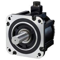
Servo motor Motor with electromagnetic brake: Straight axis
|
Model |
SV3-B100AS *1 |
SV3-B150AS *1 |
SV3-B200AS *1 |
SV3-B300AS *1 |
SV3-B500AS *1 |
|||
|
Image |
|
|
|
|
|
|||
|
General specifications |
Applicable servo amplifier |
SV3-100L2 |
SV3-150L2 |
SV3-200L2 |
SV3-300L2, SV3-500L2 |
SV3-500L2 |
||
|
Rated output |
0.85k W |
1.3k W |
1.8k W |
SV3-300L2: 2.4k W |
4.4k W |
|||
|
Rated torque |
5.39 N·m *2 |
8.34 N·m *2 |
11.5 N·m *2 |
SV3-300L2: 15.1 N·m |
28.4 N·m *2 |
|||
|
Instant maximum torque |
14.2 N·m |
23.3 N·m |
28.7 N·m |
SV3-300L2: 45.1 N·m |
71.6 N·m |
|||
|
Rated current |
6.9 Arms |
10.7 Arms |
16.7 Arms |
SV3-300L2: 19.6 Arms |
32.8 Arms |
|||
|
Instant maximum current |
17 Arms |
28 Arms |
42 Arms |
SV3-300L2: 56 Arms |
84 Arms |
|||
|
Rated rotation speed |
1,500 min-1 |
|||||||
|
High rotation speed |
4,000 min-1 |
|||||||
|
Torque constant |
0.859 N·m/Arms |
0.891 N·m/Arms |
0.748 N·m/Arms |
0.826 N·m/Arms |
0.932 N·m/Arms |
|||
|
Rotor moment of inertia |
16.0 ×10⁻⁴ kg·m2 |
22.0 ×10⁻⁴ kg·m2 |
28.1 ×10⁻⁴ kg·m2 |
53.9 ×10⁻⁴ kg·m2 |
75.4 ×10⁻⁴ kg·m2 |
|||
|
Rated power rating |
18.2 kW/s |
31.6 kW/s |
47.1 kW/s |
SV3-300L2: 42.3 kW/s |
107 kW/s |
|||
|
Rated angle acceleration |
3,370 rad/s2 |
3,790 rad/s2 |
4,090 rad/s2 |
SV3-300L2: 2,800 rad/s2 |
3,770 rad/s2 |
|||
|
Excitation method |
Permanent magnet |
|||||||
|
Position/speed detection encoder |
Resolution |
26 bit |
||||||
|
Type |
Absolute (ABS) type |
|||||||
|
Operating environment |
Enclosure rating |
Completely closed, self-cooling, IP67 standard (excluding connector and axis through-hole) |
||||||
|
Operating ambient temperature |
0 to +60°C 32 to 140°F (reduced ratings at +40°C 104°F or higher) |
|||||||
|
Storage ambient temperature |
-20 to +60°C -4 to +140°F |
|||||||
|
Operating/storage ambient temperature |
20% to 80% RH (No condensation) |
|||||||
|
Operating atmosphere |
Indoors (No corrosive gas, flammable gas, oil mist, or dust) |
|||||||
|
Altitude |
2,000 m 6,561.7' or less (reduced ratings at 1,000 m 3,280.8' or more) |
|||||||
|
Vibration rank |
V15 |
|||||||
|
Vibration resistance |
49 m/s2 160.8 ft/s2 with servo motor flange surface as reference (up/down, left/right) |
|||||||
|
Impact resistance |
490 m/s2 1,607.6 ft/s2 with servo motor flange surface as reference, 2 times |
|||||||
|
Isolation rank |
Class F |
|||||||
|
Min. insulation resistance |
500 VDC 10 MΩ or more with insulation resistance meter |
|||||||
|
Isolation voltage tolerance |
1,500 VAC for 1 minute |
|||||||
|
Approved standards |
UL/CSA standards |
UL1004-1, UL1004-6, CSA C22.2 No.100 |
||||||
|
CE marking |
Low-voltage directive |
EN60034-1, EN60034-5 |
||||||
|
EMI |
EN55011 Class A, EN61800-3, EN61000-6-4 |
|||||||
|
EMS |
EN61800-3, EN61000-6-2 |
|||||||
|
North America EMI standard |
FCC Part 15 B, ICES-003. Class A |
|||||||
|
Allowable load inertia moment |
5×*3 |
5× |
SV3-300L2: 3× |
5×*3 |
||||
|
Approx. weight |
7.5 kg 16.53 lb |
9.0 kg 19.84 lb |
11.0 kg 24.25 lb |
19.5 kg 42.99 lb |
23.5 kg 51.81 lb |
|||
|
Electromagnetic brake specifications |
Capacity |
10 W |
18.5 W |
|||||
|
Rated voltage |
24 VDC (−0%/+10%) |
|||||||
|
Rated current (@20°C 68°F) |
0.41 A |
0.77 A |
||||||
|
Holding torque |
12.7 N·m |
19.6 N·m |
43.1 N·m |
|||||
|
Release time |
100 ms |
170 ms |
||||||
|
Operating time |
80 ms |
100 ms |
||||||
|
*1 The open and operation times of the electromagnetic brake depend on the discharge circuit. |
||||||||
