3D Scanner

In recent years, there has been a growing demand to expedite the development and market release of products. This has led to increased emphasis on a development approach known as Concurrent Engineering (CE) within the product development field. Concurrent Engineering emphasizes simultaneous collaboration across different stages of the development process. Moreover, the integration of IT tools like CAD (Computer-Aided Design), CAM (Computer-Aided Manufacturing), PDM (Product Data Management), and PLM (Product Lifecycle Management) plays a pivotal role in facilitating effective Concurrent Engineering practices. We'll discuss the core principles of concurrent engineering, which aim to reduce development time, along with the necessary IT tools. We'll also explore how KEYENCE's 3D scanner, the VL Series, can be instrumental in this process. We'll delve into the shortcomings of traditional development methods, solutions offered by concurrent engineering, and practical steps for utilizing the VL Series to achieve these goals.
What is Concurrent Engineering
Concurrent Engineering, or CE, is a development method that aims to shorten the development period and reduce costs by advancing multiple processes simultaneously during product development. It is also often referred to as "CE," an abbreviation of Concurrent Engineering.
Traditional development methods progress in stages, with "upstream processes" (such as planning and design), followed by "downstream processes" (like prototyping and design). This sequential approach is often referred to as "Waterfall" development, as it progresses like the flow of water. In contrast, the basic concept of Concurrent Engineering is to carry out each process in parallel, thereby shortening the development period.
According to the Japanese Industrial Standards (JIS), Concurrent Engineering is defined as "a technology that carries out production activities simultaneously and concurrently by integrating processes related to the entire lifecycle of a product and exchanging information with each other."
The concept of Concurrent Engineering was born in the United States in the 1980s. In Japan, it has been adopted primarily by major automobile manufacturers and has recently spread to a wide range of manufacturing industries, including home appliances and heavy industries. Concurrent Engineering is also increasingly being adopted by small and medium-sized manufacturers as a means of improving their development and manufacturing processes. Besides manufacturing, Concurrent Engineering is also closely linked with both Agile and Lean software development methodologies.
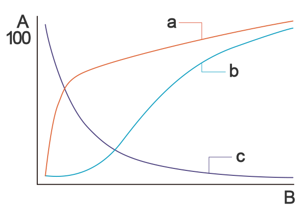
A: Cost (%), B: Process, a: Cost determination, b: Incurred cost, c: Ease of change
It is often said that 70% of development costs are determined in the early stages of design, making product planning and conceptual design extremely important processes. In Concurrent Engineering, members from different departments like sales, development, and manufacturing collaborate and progress together from the initial stages of design.
One of the key components of being able to implement Concurrent Engineering in the design phase in order to improve product quality and precision is known as Front-Loading.

Concept of Front-Loading
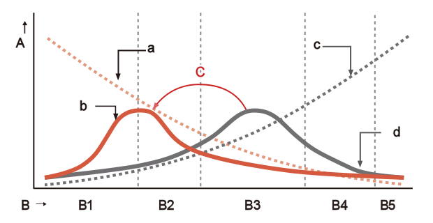
A: Cost, B: Progress of the Project, C: Advancing the Peak, B1: Planning, B2: Basic Planning, B3: Detailed Design, B4: Manufacturing, B5: Maintenance and Management, a: Ease of Change, b: Ideal Design Workload, c: Cost of Change, d: Current Design Workload
Front-Loading refers to the idea of applying load (i.e. investing effort) early (i.e. at the front) in the design process to enhance the quality of the design.
In manufacturing, if defects occur in later stages, it makes corrections and rework more difficult, impacting the delivery schedule and cost. In today's world, where reducing lead time and cost for market introduction of products is prioritized, defects in later stages can be fatal. To mitigate such challenges and attain reductions in lead time and cost savings during development, implementing Front-Loading and Concurrent Engineering can be essential.

Advantages and Disadvantages of Concurrent Engineering
Advantages
The benefits gained from Concurrent Engineering include shorter delivery times, cost reduction, and quality improvement.
By proceeding with design and production in parallel, the development period can be shortened, and design changes can be addressed at the production stage. This not only shortens the development period but also minimizes corrections in later stages. As a result, the product lead time can be shortened, enabling the fastest possible product launch in the market. Furthermore, by preventing unnecessary design changes in advance, rework is reduced, leading to more efficient product development. As the design and manufacturing departments collaborate and communicate throughout the development process, benefits such as improved product quality are also realized.
Being able to quickly launch products in the market enhances customer satisfaction by facilitating the production of diverse products in small batches and the timely introduction of products tailored to meet customer demands. Achieving this feat is challenging with traditional waterfall development, characterized by lengthy development periods.
Disadvantages
While Concurrent Engineering offers numerous advantages, it also presents challenges, with communication being the most significant. Collaboration across departments is crucial as development progresses regardless of upstream or downstream processes. Inadequate communication systems for information sharing not only hinder the realization of benefits like shorter delivery times, cost reduction, and quality improvement but can also lead to confusion throughout the development process.
In manufacturing, tasks often rely heavily on individuals, posing challenges. To address this, establishing rules and integrating IT tools like CAD, CAM, PDM, and PLM becomes crucial. These tools facilitate information sharing and communication but require effective implementation.
Tools Required for Concurrent Engineering
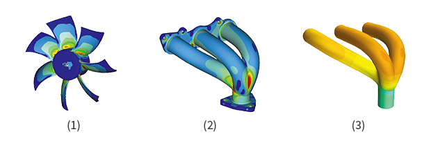
(1) Example of fan stress analysis (2) Example of manifold stress analysis (3) Example of manifold fluid analysis
In Concurrent Engineering, effective interdepartmental communication is crucial. Introducing specific IT tools is essential, especially with globalization's advancement, requiring seamless communication, even across overseas bases. Here, we highlight key IT tools vital not only for Concurrent Engineering but also for Front-Loading.
- CAD(Computer Aided Design)
CAD stands for "Computer Aided Design", which refers to design supported by computers. It is also used as a general term for tools that perform design and drafting on a computer.
CAD is broadly divided into "2D CAD", which creates 2D flat drawings, and "3D CAD", which models three-dimensional images that can visualize complex shapes. Both are different from traditional paper drafting, and the advantage is that management, sharing, modification, and reuse can be easily performed by digitizing. In Concurrent Engineering, digitization by CAD is a mandatory item for data sharing between departments. - CAM(Computer Aided Manufacturing)
CAM stands for "Computer Aided Manufacturing", which refers to manufacturing supported by computers. Like CAD, it is also used as a general term for tools that perform manufacturing with computer support.
Specifically, when manufacturing or processing products or parts, it is a tool that creates NC (Numerical Control) programs necessary for machine tool processing based on the drawings created by CAD. Tools called "CADCAM", which combine the function of outputting design data created by CAD and manufacturing by CAM, have become common. - CAE(Computer Aided Engineering)
CAE stands for "Computer Aided Engineering", which refers to performing simulations and analyses such as structural analysis, mechanism analysis, and thermal fluid analysis on a computer. It is also used as a general term for software that performs these analyses.
Specifically, based on the data created by CAD, it simulates invisible physical phenomena such as stress, temperature, electromagnetic waves, and vibrations, and evaluates the performance and safety of products by visualizing the data. The advantage of CAE is that evaluations can be conducted on a computer without the need for prototypes, saving time and costs while providing data for communication. However, it's still essential to create prototypes rather than solely relying on CAE.
Software tools are also useful for reverse engineering
Software, such as CAD and CAM, which we introduced as necessary for concurrent engineering, are also useful for reverse engineering. In general product development, design drawings are created according to requirements, followed by analysis and prototyping, and then production. In contrast, reverse engineering involves measuring a product or part and creating a drawing. While this may seem like copying a product, the essence of reverse engineering is to disassemble or analyze an existing product to reveal its mechanisms, specifications, components, technology, design, etc. The main goal is to improve quality, reduce design time, shorten development costs, and quickly bring the product to market. In addition, it is a development method used for restoring old products that no longer have drawings. In reverse engineering, CAD, CAM, and CAE are indispensable. In addition, various measuring devices and equipment like 3D scanners are necessary to understand the shape of the product.
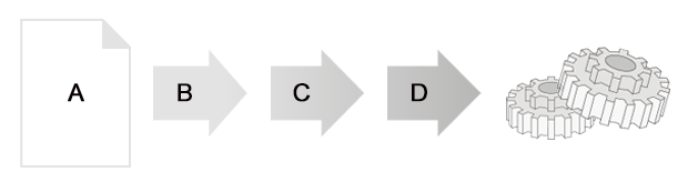
A: CAD data design document,B: Analysis,C: Prototyping,D: Production
General manufacturing process

A: CAD data design document,B: Analysis & Data Processing,C: Shape Measurement
Reverse Engineering
Challenges in the Traditional Development Process
Here, we summarize the challenges in traditional waterfall development.
Longer Development Lead Time
In traditional waterfall development, the manufacturing department only gets involved after the planning, design, and prototyping stages, which leads to a longer development lead time and a significant delay in market introduction. Furthermore, if the development lead time is extended, development costs will also increase. As mentioned earlier, it is said that 70% of the development cost is determined at the initial design stage. Utilizing reverse engineering can be an effective measure to prevent the prolongation of the development lead time.
Delays Due to Defects in the Manufacturing Process
If there are defects at the manufacturing stage, there will be setbacks such as specification changes and mold modifications, which result in significant costs and labor. Furthermore, if specification changes or mold modifications occur, delivery dates may be extended, potentially delaying market introduction. For example, introducing a development process that incorporates CAE to repeat tests in advance, or using a 3D printer to create prototypes from an early stage, could be effective measures.
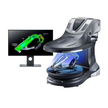
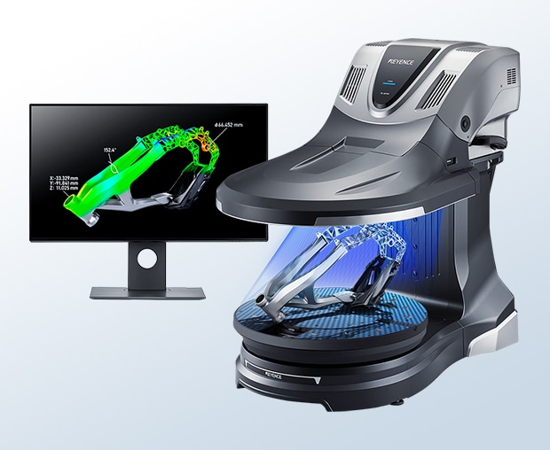
Shortening Development Lead Time with the VL Series
In concurrent engineering, the incorporation of front-loading and reverse engineering concepts can shorten the development lead time. Here, CAD data plays a crucial role. In reverse engineering, it is essential to digitize from the actual object to CAD, and CAD is indispensable for utilizing CAM and CAE. This is where KEYENCE's 3D scanner-type three-dimensional measuring machine, the "VL Series", comes into play. From here, we will introduce the benefits of introducing the "VL Series" for realizing concurrent engineering.
Benefit 1: Shortening Development Lead Time through Reverse Engineering
A key feature of KEYENCE's 3D scanner-type three-dimensional measuring machine, the "VL Series", is its ability to place the target object on the stage and perform a 360° scan in as fast as 8 seconds in a single shot. It captures products quickly and accurately, and makes it easy to create CAD data. It allows for efficient measurement work and immediate digitization, making it powerful in reverse engineering. Traditionally, it was necessary to disassemble the product, measure each part, and create a drawing, but with the "VL Series", the workload can be significantly reduced. Reverse engineering becomes more accessible, effectively contributing to a significant reduction in development lead time.
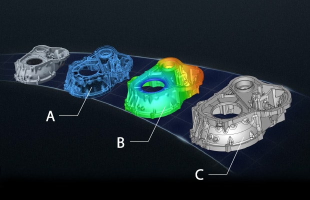
A: Point cloud data, B: Polygon data, C: CAD data
Benefit 2: Collaboration with 3D Printer, Significantly Shortening Prototype Time
KEYENCE's 3D scanner-type three-dimensional measuring machine, the "VL Series", 3D scans prototypes or products and outputs STL data optimized for 3D printing. This data can be imported into a 3D printer for modeling. Furthermore, the shape can be modified afterward, leading to process improvements. In concurrent engineering, previewing at the design stage is extremely important. Prototyping is necessary for this, but by utilizing the "VL Series" and a 3D printer, the time and cost of prototyping can be significantly reduced. This ultimately leads to a reduction in development lead time.
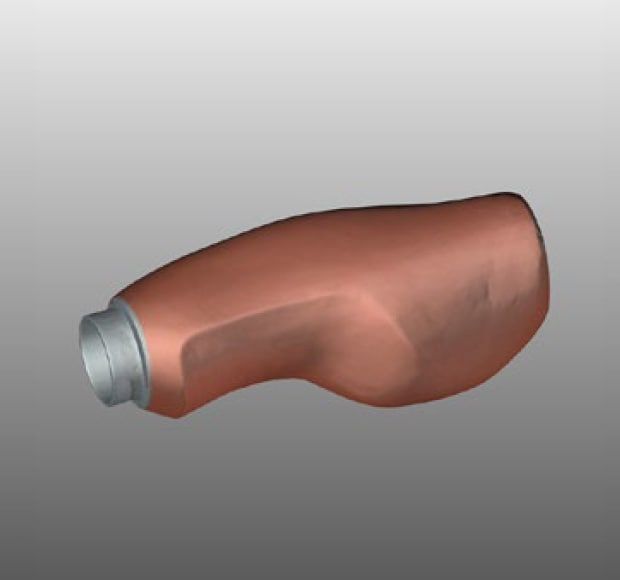
Scanned data from bicycle grips
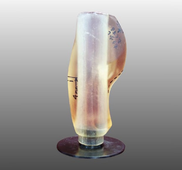
Prototyping with 3D printers
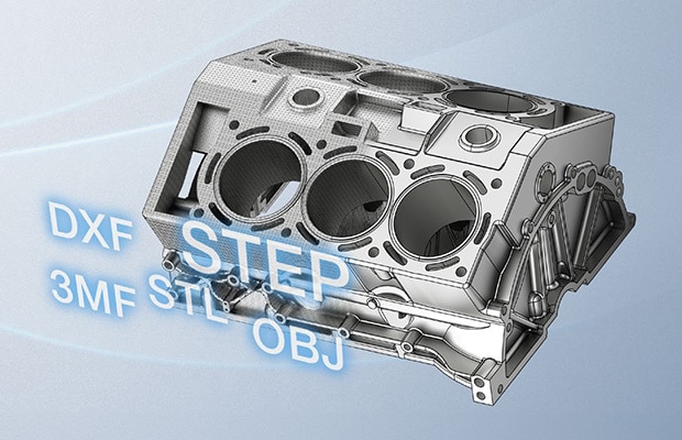
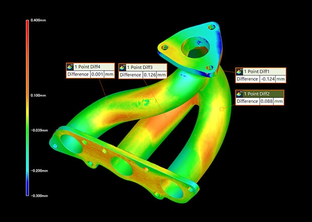
Benefit 3: Easy CAD Conversion, Can Also Be Used for CAE Analysis
By scanning with KEYENCE's 3D scanner-type three-dimensional measuring machine, the "VL Series", you can easily convert prototypes, etc., into CAD. This data can also be used for CAE analysis, making verification easy and preventing defects in advance. By overlaying the scanned data and the reference data, you can visualize whether the product fits within the intersection, and after sufficient evaluation, you can move to the production process, which helps prevent setbacks. Also, the company license allows for data exchange between development, design, quality assurance, and manufacturing using the same software, making it easier to share information, which is effective in realizing concurrent engineering. Sharing the data of prototypes at the development and design stages with the person in charge of the manufacturing process, and receiving feedback and making corrections in advance, can prevent setbacks such as modifications in later processes.
Discover how the VL Series 3D scanner revolutionizes quality control across industries, ensuring unmatched efficiency and reliability in your measurement processes. Request a demo today!
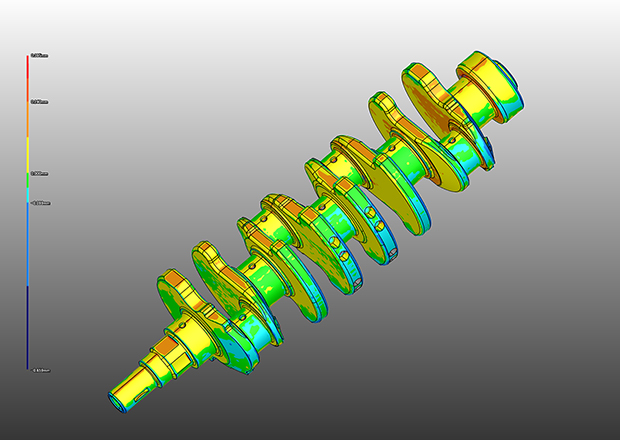
3D comparative measurement

Digitization of Prototypes and Products Contributes to Shortening Development Lead Time!
With KEYENCE's 3D scanner-type three-dimensional measuring machine, the "VL Series", it becomes easy to digitize prototypes and products, and information sharing and feedback, which were challenges in concurrent engineering, can be performed efficiently. As a result, it is effective in shortening the development lead time.
- With a single shot, it can digitize prototypes or products in an instant with a 360° scan in as fast as 8 seconds.
- Sharing the scanned data between departments makes simultaneous verification and work easier.
- It can easily measure complex shapes and free-form shapes, and can be used regardless of the product.
- Comparisons with intersections and other data can be displayed in a color map, making it easy to understand even for non-designers.
- In collaboration with a 3D printer, the time and cost of prototype verification can be significantly reduced.
Concurrent engineering has many challenges, such as information sharing, communication, and CAD digitization. By utilizing KEYENCE's 3D scanner-type three-dimensional measuring machine, the "VL Series", these challenges can be solved, effectively contributing to a reduction in development lead time.
Get detailed information on our products by downloading our catalog.
View Catalog