3D Scanner
Although the term “3D printers” has become widely used, the correct term under the ASTM standards is “Additive Manufacturing Technology.” This page introduces additive manufacturing and various applications of KEYENCE’s VL Series of 3D Scanner CMMs.
Additive Manufacturing
Manufacturing that involves cutting and modeling materials is known as subtractive manufacturing. Manufacturing that involves layering materials with a 3D printer is known as additive manufacturing.
Target

Subtractive manufacturing

The target is manufactured by cutting away material from a round bar, block, or other shape.
Additive manufacturing
The target is manufactured by layering resin, powder, or other material.
Advantages of additive manufacturing
[Ability to manufacture complicated targets]
Targets with hollow areas or overhanging shapes that cannot be created with cutting tools can be manufactured.
Not only is it possible to model complicated shapes, but it can also reduce weight.
Target

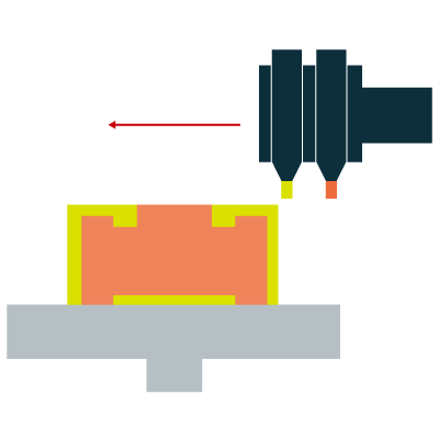
Subtractive manufacturing
Hollow shapes (A) cannot be created, and overhanging shapes (B) are difficult to machine.
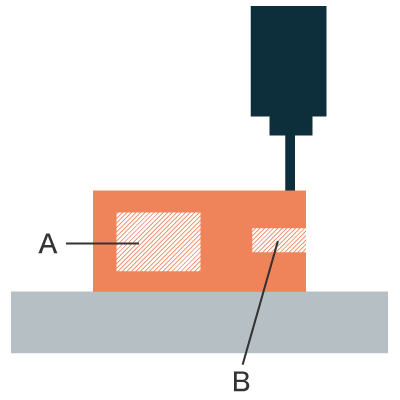
Additive manufacturing
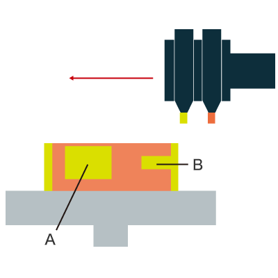
Hollow shapes (A) and overhanging shapes (B)
can be easily manufactured.
Ideal for small-lot multi-variety production with stringent deadlines
Because modeling requires only 3D data and no molds or jigs, additive manufacturing is ideal for small-lot multi-variety production. Another advantage is the ability to meet stringent manufacturing deadlines.
Reduced number of parts
With conventional subtractive manufacturing, multiple parts must be welded or soldered together. With additive manufacturing, however, targets can be created as a single piece, reducing the number of parts needed for manufacturing. Because the material is layered during modeling, material costs can be reduced.
Automation
Manufacturing is possible using only 3D CAD data even without any specialized knowledge.
Manufacturing can also be performed anywhere in the world so long as a 3D printer is available.
Seven methods of additive manufacturing outlined in the ASTM standards
Commercial 3D printers that are available to the public typically utilize the material extrusion method. However, with additive manufacturing, the method being used will vary depending on the material being modeled.
Material extrusion
Flowable material is extruded through a nozzle and selectively solidified.
Material: Thermoplastic resin
Sheet lamination
Sheet materials are layered and bonded together.
Material: Paper, resin, metal foil
Material jetting
Droplet-like material is injected and selectively solidified.
Material: Light-curable resin, wax
Binder jetting
A liquid binder is injected into a powder material and selectively solidified.
Material: Plaster, plastic
Directed energy deposition
The position of focused thermal energy is controlled during material feeding to selectively melt and solidify the material.
Material: Metal
Vat photopolymerization
Liquid light-curable resin (photosensitive resin) in a tank is selectively cured using light (photopolymerization reaction).
Material: Light-curable resin
Powder bed fusion
Areas of a powder bed are selectively melted and bonded using thermal energy.
Material: Metal, resin, ceramic
3D Scanner Applications in Additive Manufacturing
Using a 3D scanner makes it possible to create drawings of objects for which drawings are not originally available.
This is known as reverse engineering and can be used in the following situations.
- When drawings are not available from the supplier requested to design the part
- When designing using the actual shape of a product that incorporates the part
- When only the product is available from the client without any drawings
- When making a part that is different from the drawing but the same shape as the actual part
- When drawings for older parts are only available on paper
Conventional manufacturing process
(1) CAD data design
(2) Analysis
(3) Prototyping
(4) Production
(5) Product
Reverse engineering
(1) Product
(2) Shape measurement
(3) Analysis/data processing
(4) CAD data design
Reverse engineering
Reverse engineering refers to the disassembly and analysis of software, hardware, and other existing products to determine the operating principles, technical elements, and other information.
In manufacturing, reverse engineering usually refers to obtaining data by measuring the shape of a clay model or an actual product and then creating (generating) CAD data based on those measurements. In recent years, 3D CAD and 3D scanners have become increasingly popular, and reverse engineering is rapidly growing in Europe and the US.
Challenges with reverse engineering
[Measurement accuracy: Large measurement errors / Operator-based variations in results]
When creating drawings from an actual product, accurate measurements are essential. Using calipers or height gauges can result in large measurement errors and variations between operators.
[Measurement time: Measurements take a long time]
As the complexity of the shape increases, so do the number of measurement points, resulting in measurements taking a long time.
[Data quality: Incorrect reproduction of shapes]
Even when using a 3D scanner to scan a shape and create drawings, problems such as poor data quality and low resolution can arise, resulting in incorrect reproduction of the shape.
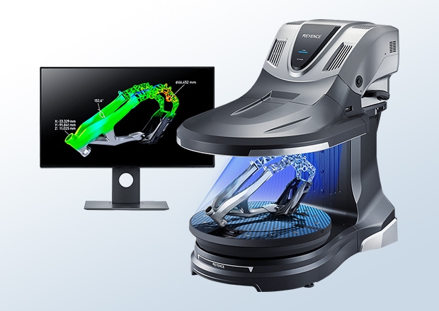
Solutions Made Possible with the VL Series 3D Scanner CMM
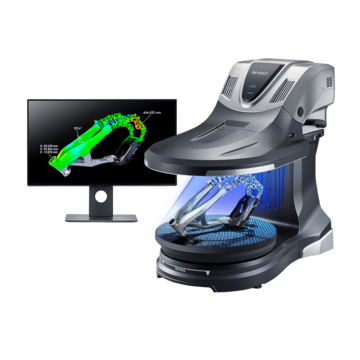
KEYENCE’s VL Series of 3D scanner CMMs can solve various problems with conventional methods to make reverse engineering easy.
[Measurement accuracy: High-accuracy measurements]
Take advantage of a guaranteed accuracy of ±10 μm and repeatability of 2 μm along the X, Y, and Z axes. High-accuracy measurements are possible with no variations between operators.
[Measurement time: One-shot measurement in about 30 seconds]
Scanning can be completed with a single shot in about 30 seconds. This makes measurement of the desired locations quick and easy even for complicated shapes.
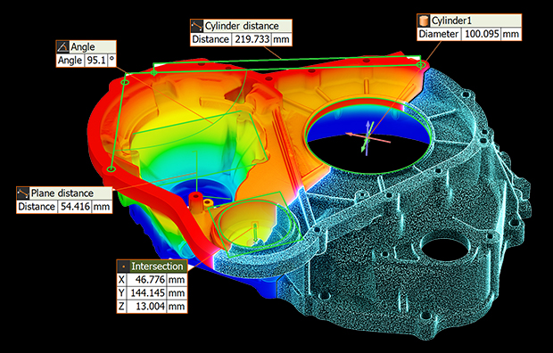
[Data quality: Sample-specific scan settings]
Scan settings can be configured to suit the size and shape of the sample.
The shape of any sample can be reproduced with high data quality simply by selecting the suitable settings—high-definition mode for delicate shapes and a high magnification camera for small objects.
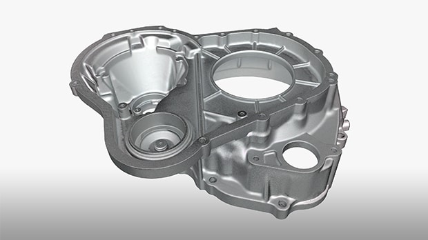
3D data creation
Scan data
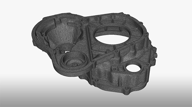
STL data
* Use of dedicated software or external services is required to convert scanned data to CAD data.
2D data creation
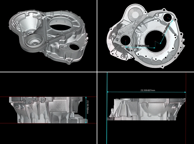
2D measurement
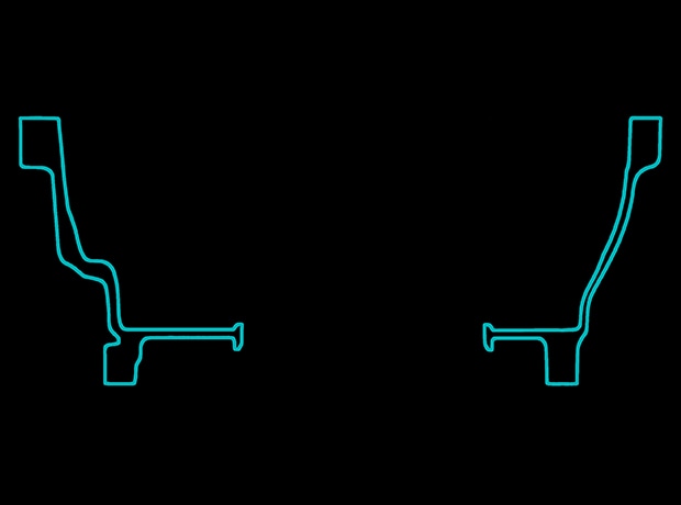
Cross-section measurement (DXF output)