3D Scanner
Drawing is a method of press forming that is used to produce products such as metal cups, containers, and kitchen sinks. Said to be the most difficult press forming method, defects such as uneven thickness and cracking occur easily as a result of stress, friction, and other factors during forming. For this reason, it is essential to perform measurement of workpiece thickness and check for defects such as cracks and wrinkles after forming.
This section explains the typical drawing methods and the types of defects that occur in drawn products. It also introduces problems in conventional measurement methods and a solution to these problems.
Drawing
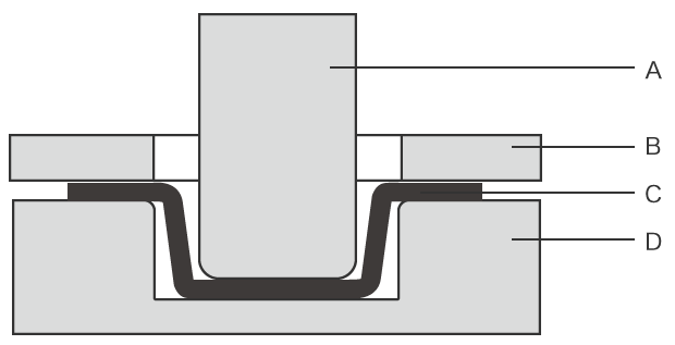
A : Punch B : Blank holder C : Sheet metal blank D : Die
Drawing is a method of press forming that forms a sheet metal blank into a seamless container that includes a bottom.
Drawing forms a sheet metal blank into the shape of a cup or container by pressing a die called a punch into the blank that is held between the die and blank holder. Drawing in which the pressing depth exceeds the punch radius is called deep drawing. If a sheet metal blank cannot be formed with a single press due to its material, thickness, or other factor, it can be formed gradually in multiple presses.
One advantage of drawing is that it can produce complex-shaped products with fewer steps than cutting and forging, which involve processes such as cutting away excess parts or hammering.
Pressure Application Methods Used by Drawing Machines
Drawing machines are roughly categorized into two types: mechanical presses and hydraulic presses. Mechanical presses transmit the rotational force of a motor to the punch in order to apply pressure. Hydraulic presses use hydraulic pressure to slide the punch in order to apply pressure.
Mechanical presses feature fast forming speeds and good maintainability. However, they are only able to move the punch in a limited range and pressure adjustment is not possible, making them unsuitable for deep drawing. Hydraulic presses on the other hand can adjust the amount of pressure applied and feature a longer punch stroke and easier forming speed adjustment compared with mechanical presses. Hydraulic presses also do not produce overload. However, they need to be maintained on a regular basis to adjust the hydraulic pressure and prevent leakage of hydraulic fluid.
Drawing is most often performed using mechanical presses, and hydraulic presses are used for drawing that cannot be performed by mechanical presses. In recent years, presses have been developed that allow high-precision pressure adjustments and are equipped with servo motors that do not limit the punch motion.
Types of Drawing
Types of drawing include cylindrical cup drawing, square cup drawing, and irregular shape drawing, as well as a type of drawing for more complex shapes. This section introduces three typical types.
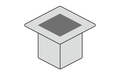
Cylindrical cup drawing
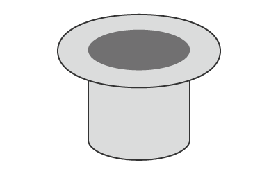
Cylindrical cup drawing forms a sheet metal blank into a cylindrical shape. This is the most basic type of drawing, and is used to create products in shapes such as cups and bowls.
Square cup drawing
Square cup drawing forms a sheet metal blank into a square tube shape, and is used to create products in shapes such as square containers and cases. The corners of the drawn products are susceptible to cracking and wrinkling.
Irregular shape drawing
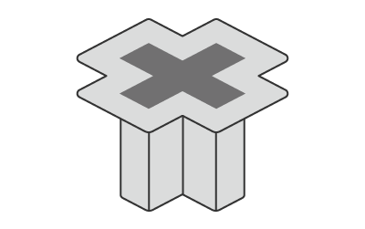
Irregular shape drawing is used to form complex shapes. It can be used to form shapes that are not cylinders or square tubes such as fuel tanks and covers, as well as ribs that increase surface strength.
Drawing Defects
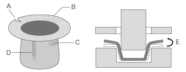
A : Cracking B : Flange wrinkle C : Wrinkle, shock line D : Galling E : Springback
This section explains the types and phenomena of defects that occur in pressing. Many types of defects occur in pressing, but this section focuses on the following typical defects.
Cracking
Drawn sheet metal blank hardens and becomes brittle. Residual stress and an imbalance of tensile and compressive forces occur in the brittle sections, causing cracking.
Wall break
This is a cracking defect that occurs on walls. Walls in corners may crack or fracture when deep drawing is performed using thin sheet metal.
Bottom falling off
Stress concentrates at the rounded parts of the punch, and results in cracking of the wall around the bottom in locations where the contact area is small.
Flange cracking
This kind of cracking may occur when the deformation resistance of the die shoulder exceeds the yield point of the sheet metal blank.
Body cracking
This defect may occur during tapered drawing or hemisphere drawing when a sheet metal blank is fixed with excessively strong force.
Season cracking
This is cracking that occurs a few days after drawing. The material hardens after drawing, and the sections that have become more brittle crack due to residual stress. This defect is often seen in stainless steel products and brass products, and may also be caused by fine cracks in the sheet metal blank.
Wrinkle
This defect is caused by the tensile force and compressive force that are applied to the sheet metal blank during drawing.
Edge wrinkle, wall wrinkle
Edge wrinkles form at parts formed by rounded corners of the die. Wrinkles also form on walls below parts formed by rounded corners of the die. These defects are caused when the drawing clearance is too large.
Body wrinkle
During tapered drawing or hemisphere drawing, wrinkles can form on the body. In some cases, this defect is caused when the sheet metal blank is not effectively restrained at the rounded corners of the die and punch.
Flange wrinkle
These defects occur on the flange. They can occur when the sheet metal blank is not sufficiently fastened in place.
Shock line
This is a defect which occurs at the start of drawing. It occurs as a result of tension applied to the sheet metal blank held by the blank holder, reducing the thickness at the rounded corners of the die.
Galling
This is deep scratching that occurs when the metalworking oil film between the die and sheet metal blank is broken, causing the blank to directly contact the die or punch. Galling occurs in the direction of punch movement, and grows larger as drawing proceeds.
Springback
Springback is a phenomenon in which a drawn workpiece returns slightly towards its original shape due to residual stress inside the formed part. Springback can cause the following defects.
Angle change
The angle of the bend part changes due to the difference in stress in the sheet thickness direction.
Wall warpage
The wall becomes warped due to the difference in stress in the length direction.
Twisting
This is a defect in which the entire part becomes twisted due to the difference in stress in the sheet thickness direction and to stress acting towards the inside of the surface.
Warpage of the ridge line
The bending ridge line becomes warped due to the difference in stress in the sheet thickness direction.
Problems in Conventional Thickness Measurement of Drawn Products
It is extremely important to confirm that the thickness and shape of a drawn product are as intended (within tolerances). Because the thickness greatly affects the product strength, highly accurate and quantitative 3D shape measurements are particularly necessary when measuring the thickness of the entire product and the minimum thickness at indented parts.
Ordinarily, coordinate measuring machines or calipers are used for measurement, however these methods involve a number of problems. These include the difficulty in achieving accurate measurement with a coordinate measuring machine, and variation in measurement depending on the operator when using calipers.
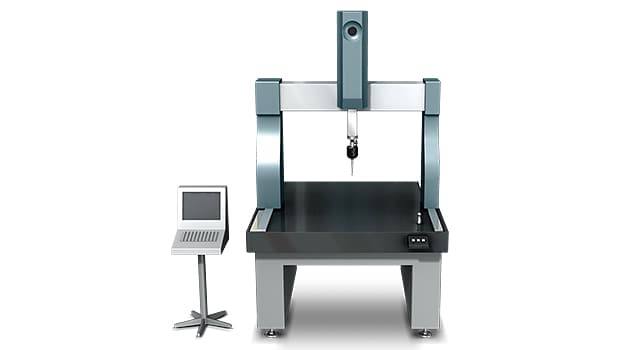
Measurement difficulties - CMM
When measuring thickness using a CMM, the target is contacted by a probe tip on both sides. When the measurement area is large, accuracy can be increased by increasing the number of measured points to collect more data.
However, using a coordinate measuring machine for thickness measurement of drawn products involves the following problems.
- Because only point data is captured, it is impossible to verify the true minimum thickness, even if hundreds of data points are captured.
- Comparison with CAD data takes time and effort due to difficulties in matching the positions in the measured data with the CAD model.
- When it comes to distinguishing between good workpieces and defective workpieces, a coordinate measuring machine can only judge based on the measurement results (tolerance levels); it cannot distinguish between them by comparing their shapes and finding the differences.
Measurement difficulties - Hand tools
Hand-held tools such as calipers and micrometers are very convenient for measurement. However, there are multiple causes which result in measurement error or variation in the measurement data.
With handheld tools, measurement conditions such as the contact force (measuring force) when measuring each point by hand and selection of the measured points differ depending on the operator. This results in variation in the measurement values and makes it difficult to obtain quantitative measurements. When the area to inspect is large, much time is required due to the many points that need to be measured. In some cases, measurement of complex shapes and freeform geometries is impossible.
Measurement Difficulties - Thickness
Reviewing the problems of conventional instruments reveals that they have the same common problem; they only capture point or line data.
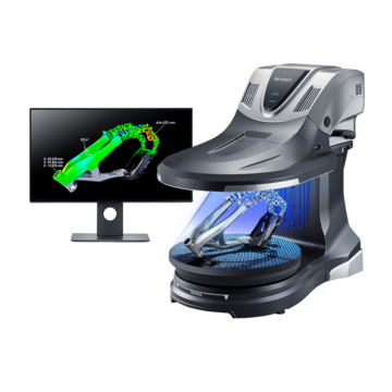
To resolve these measurement problems, KEYENCE has developed the VL Series 3D Scanner CMM. The VL Series accurately captures the 3D shape of the entire target surface without contacting the target. A 3D scan of the target on the stage can be completed in as little as one second, for high accuracy measurement of the 3D shape. This allows quantitative measurement to be performed easily without variation in the measurement results. Some specific examples of the advantages are explained below.
Advantage 1: Easy thickness measurement
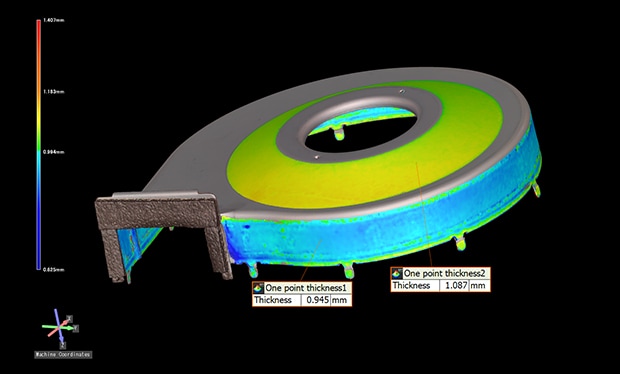
The VL Series can automatically calculate the thickness at specified points and display the differences in color. When thresholds are set for three-color display, it is possible to judge pass/fail during inspection and to compare the shapes of good products and defective products. By using a gradation display to compare the measured data with design data from prototyping, it is possible to analyze trends in thickness, allowing easy analysis of thickness reduction and distribution.
Automatic measurement of minimum thickness
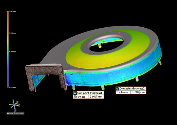
Comparison of shapes between a good product and defective product
Advantage 2: The entire 3D shape is captured
When a product with a complex shape that was produced by irregular shape drawing is measured using a CMM or calipers, measurement requires a lot of time because of the many points that must be measured. Because only individual points are measured, it is impossible to measure the true 3D shape of the target.
With the VL Series, you only need to place the target on the stage and scan it. The 3D shape of the target can be captured by non-contact means and no positioning is required. As profile measurement is also possible at any part of the target, it is possible to visualize and identify the locations and precise numerical values of shape defects.
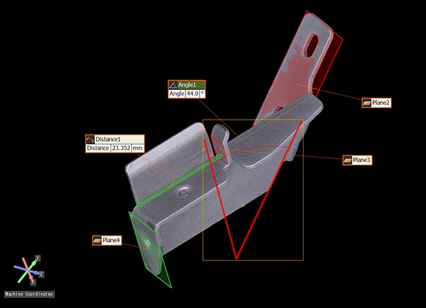
The VL Series can also measure cross-sections when comparing the acquired data with 3D-CAD data without the need to cut the workpiece. Thickness conditions in the acquired 3D data can be visualized in color. This enables thickness measurement to be performed easily without contacting the target. Defects such as springback can be detected early by checking for misalignment of cut profiles. This allows countermeasures, such as pressure adjustment to be enacted.
Cross-section comparison measurement of hinge parts
Bend angle measurement of an LCD frame
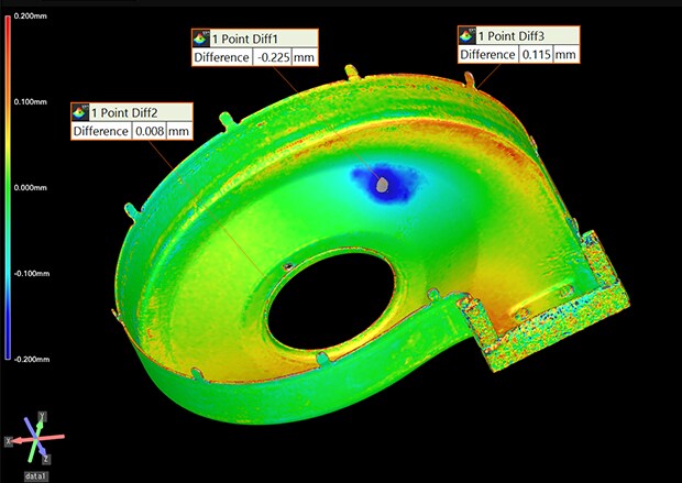
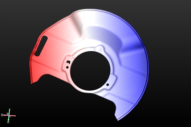
Advantage 3: Differences from 3D-CAD data can be visualized in color
It is possible to compare a product’s 3D-CAD data with the acquired measurement data for color visualization of any differences between the actual product and the design. This can dramatically reduce the number of man-hours required to analyze the shape of products.
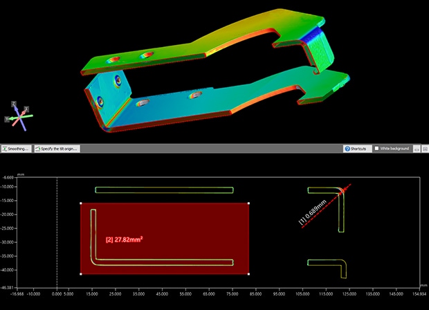
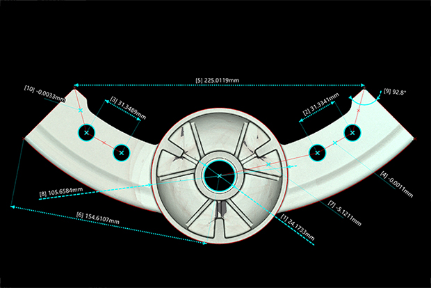
The VL Series can measure not only the edge profile of the sample, but also its 3D shape projected in 2D, heights relative to the reference point, and 2D measurements.
Discover how the VL Series 3D scanner revolutionizes quality control across industries, ensuring unmatched efficiency and reliability in your measurement processes. Request a demo today!
Comparative measurement with 3D-CAD data (automobile brake part)
XY dimension measurement
Summary: More Efficient Thickness Measure of Drawn Products
The VL Series can instantaneously and accurately measure the 3D shapes of drawn products by high-speed 3D scanning without contacting the target, which offers the following advantages:
- No positioning is required. Measurement can be performed simply by placing the target on the stage and clicking a button.
- Because the entire surface is measured, it is possible to identify all defect locations on the target, and to perform profile measurement at any desired part.
- Comparison measurement between 3D-CAD data and the acquired data can be performed.
- The 3D shapes can be displayed in a color map. By sharing visually-understandable data, it is possible to smoothly formulate and implement countermeasures against pressing defects.
- Differentiation of OK/NG products and data sharing is possible, allowing rapid analysis of NG products.
In this way, the VL Series can deliver dramatic improvements in thickness measurement efficiency and defect analysis.