KV-X Series × GC-1000
EtherNet/IP™ Connection Guide
Return to KV Series Connection Guide
KV-X Series × GC-1000 EtherNet/IP™ Connection Guide
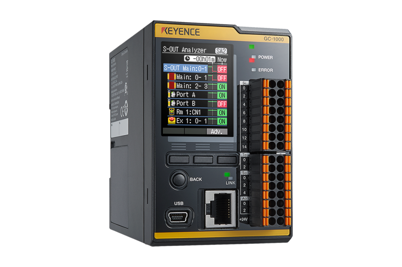
GC-1000

Contents
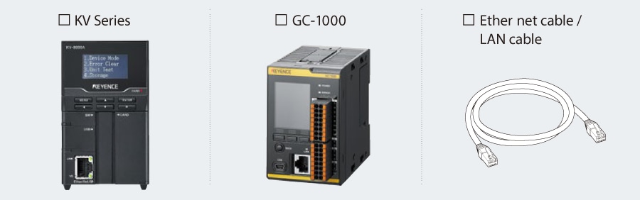
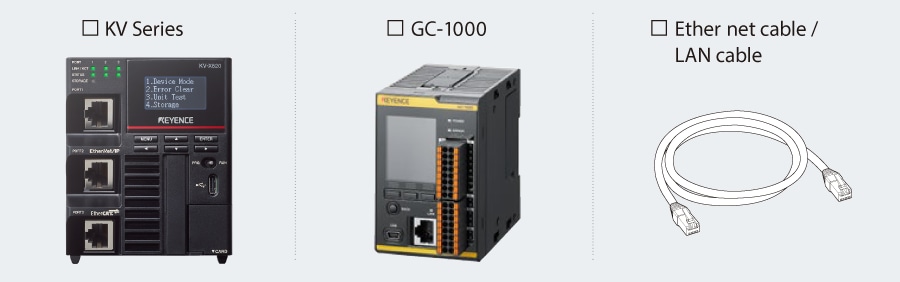
Step 1 : Checking the Equipment Required for Connection
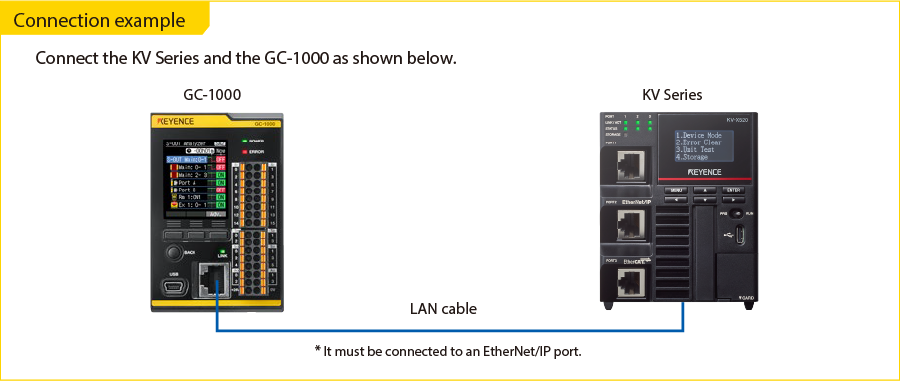
Prepare the following equipment. When using a unit other than the KV Series, replace references to the KV Series with your unit.
Communicating with the KV Series
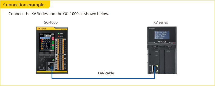
Step 2 : GC-1000 [EtherNet/IP] Settings
Use GC Configurator to configure the network settings of the GC-1000. For the example used in this guide, the following IP Addresses are assigned to the KV Series and the GC-1000:
IP address assigned to the KV Series ……………… (Example: 192.168.0.10 [default])
IP address assigned to the GC-1000 ……………… (Example: 192.168.0.1)
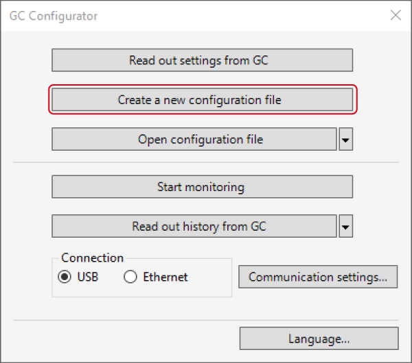
1. Connect the PC and the GC-1000 with a USB cable (OP-51580: 2 m / OP-86941: 5 m).
Start GC Configurator and click [Create a new configuration file].
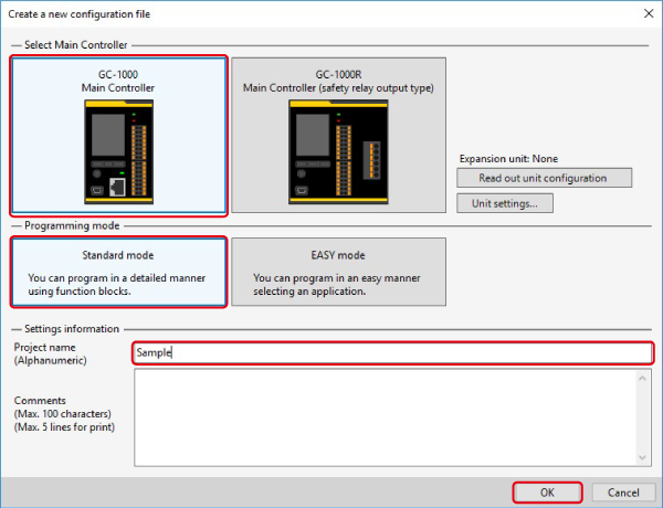
2. The [Create a new configuration file] dialog box appears. Select a main controller and programming mode and click [OK].
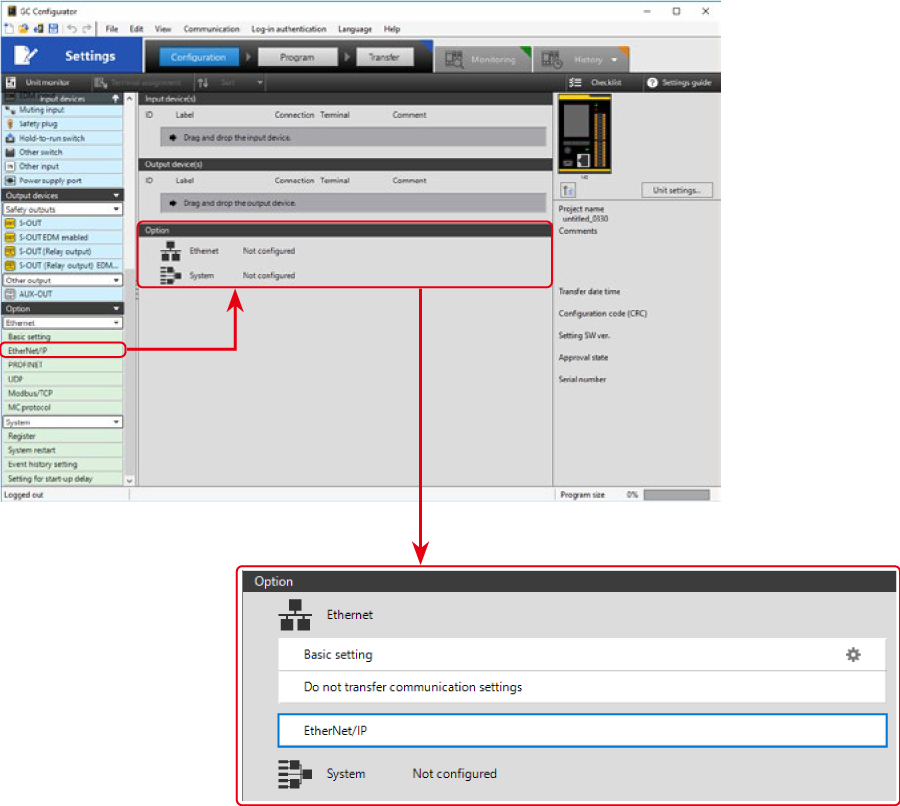
3. Double-click [Basic setting] under [Option] > [Ethernet], and then double-click [Basic setting] in the center column. The [Basic setting] dialog box is displayed. Set the IP address, subnet mask, and default gateway and then click [OK].
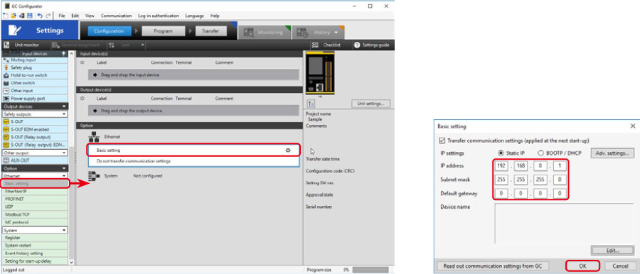
4. Drag and drop [Option] > [Ethernet] > [EtherNet/IP] onto Ethernet under Options (the area in the red frame in the figure below).
* EtherNet/IP is added to the [Option] box.
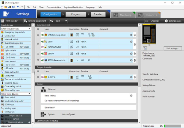
5. Configure settings for units connected to the GC-1000 with Equipment Configuration and create the safety control program with Programs.
For details on Equipment Configuration and Programs, consult the GC Series User’s Manual.
Equipment configuration example
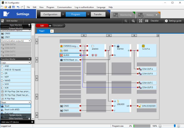
Program example
Step 3 : KV-X Series Connection Settings
This section explains how to connect with a fictitious device called "Vendor Series". Replace the "Vender Series" with the device to be connected.
One point
For the KV Series with a CPU function version of 2.0 or later, variables can be assigned to the connection of EtherNet/IP.
When assigning variables to the connection of EtherNet/IP®, check the box of “Displays the variable setting dialog when updating the EtherNet/IP settings (E)” for “Other settings” of “System settings” on the “CPU system settings” dialog.
The “CPU system settings” dialog is displayed by selecting [Display (V)] ⇒ [CPU system settings (P)] from the ”KV STUDIO” menu.
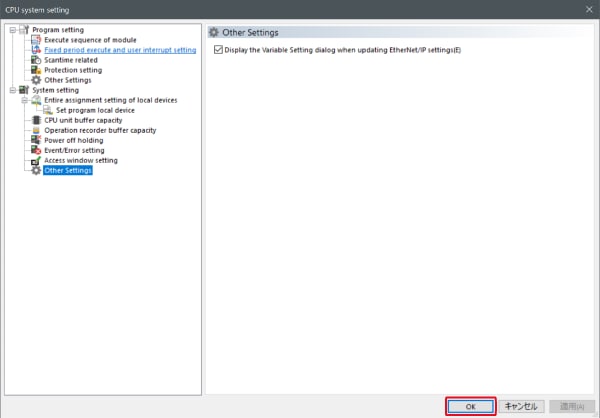
When the box of "Displays the variable setting dialog when updating the EtherNet/IP settings (E)" is checked, at the timing when the EtherNet/IP setting is updated and the changed content of the unit editor is confirmed, a dialog to assign variables to the connection is displayed.
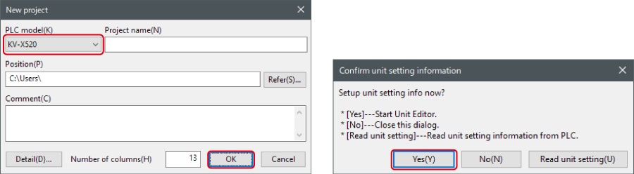
1. Start up the KV STUDIO and create a new project. Set the model option to “KV-X520” and click [OK].
A [Confirm unit configuration setting] dialog box is displayed. Click [Yes (Y)].
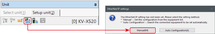
2. The unit editor is displayed. On the “Setup unit(2)” tab, click the icon of EtherNet/IP setting. A configuration type selection dialog box is displayed. Click [Manual (M)].
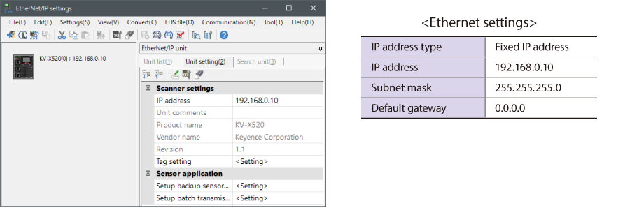
3. On the “Unit setting (2)” tab, set the IP address for KV-X Series. In this example, configure the setting as shown below.
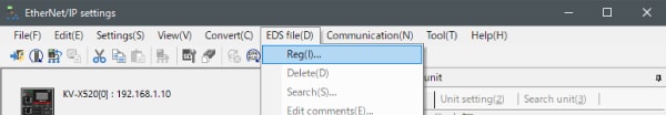
* Step 4 needs to be performed to import a sensor setting file. When the sensor setting file has already been imported, proceed to Step 5.
4. Select [EDS file (D)] → [Reg (I)] to import the KEYENCE sensor setting file(ez1 file) or EDS file.
* Download the sensor setting file from the KEYENCE website.
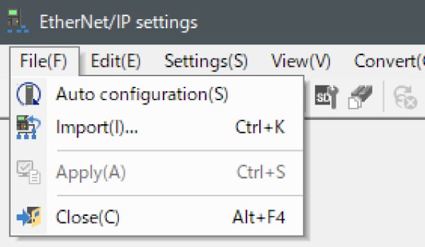
5. With the KV-X Series and the EtherNet/IP devices connected using the Ethernet cable, select [File (F)] → [Auto configuration (S)] on the [EtherNet/IP settings] window.
6. When the configuration on the unit editor differs from that of the actual device, a dialog for confirming transfer of the project is displayed. With the PC and KV-X Series connected using the USB cable, click [Yes (Y)].
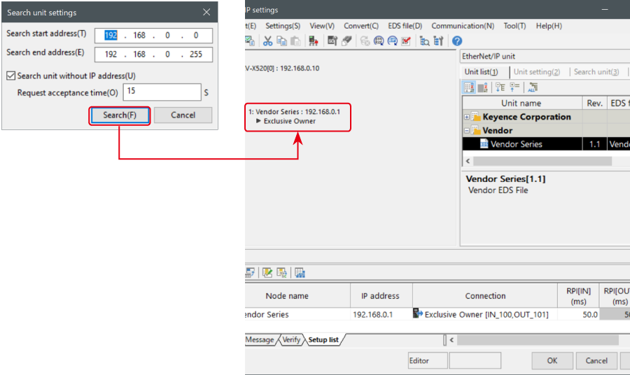
7. When transfer of the project is completed, the [Search unit settings] dialog is displayed. Then click [Search (F)]. After the auto configuration is completed, "Vendor Series" is automatically registered. Then click [OK] to close the [EtherNet/IP settings] window.
8. Click [OK] on the unit editor to exit.
One point
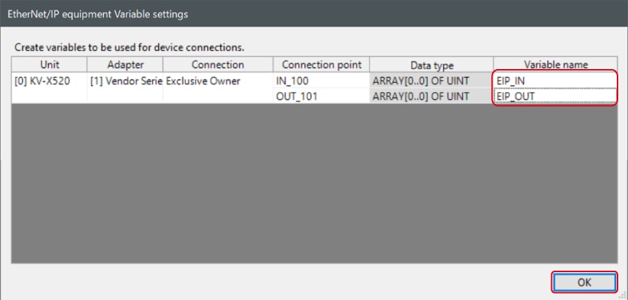
When the box of "Displays the variable setting dialog when updating the EtherNet/IP settings (E)" is checked, the [EtherNet/IP equipment Variable settings] dialog is displayed.
Enter the name of variable assigned to the connection, and click [OK].
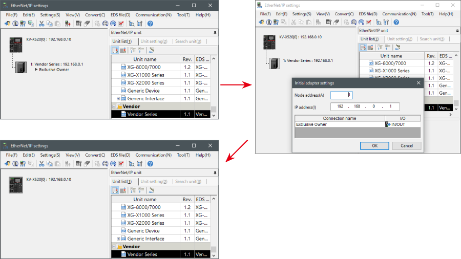
- The way of Device Configuration Settings manually
In the [Unit list (1)] tab of “EtherNet/IP Settings”, drag and drop "Vendor Series" and create a device configuration.
Transferring and Monitoring Setting Data
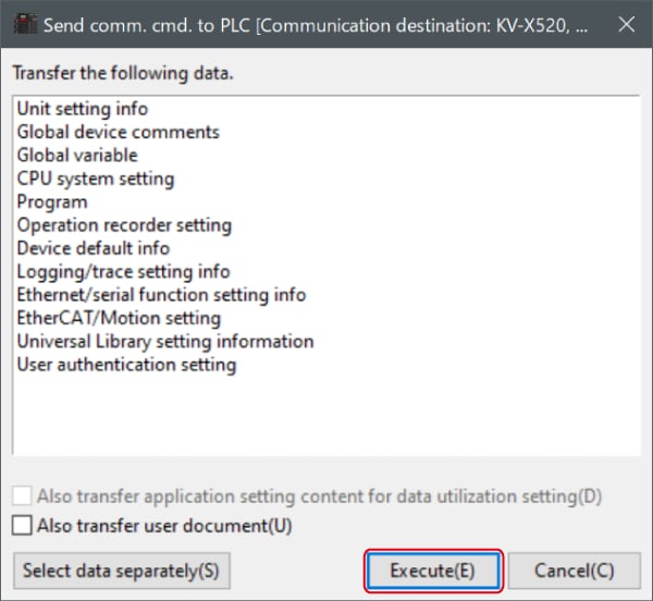
1. From the menu, select [Monitor/Simulator (N)] > [Transfer to PLC (W) → Monitor mode (C)].
In the [Send comm. cmd. to PLC] dialog box, click [Execute(E)].
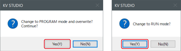
2. If the following dialog box is displayed before and after transferring the data, click [Yes] both times.
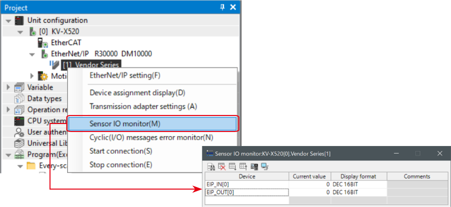
3. Right-click on “Vender Series” in the workspace, and select [Sensor IO monitor (M)].
Scores and other information can be easily monitored.
One point
The information can also be checked on a graph by starting up the real time chart monitor.
Right-click on “Sensor I/O monitor” and select [Real time chart monitor (H)].
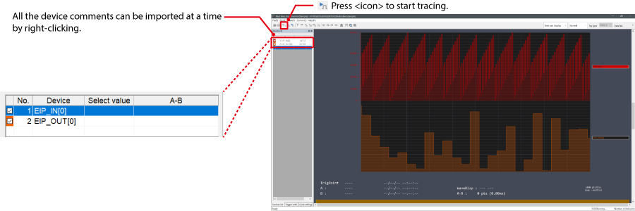
Range adjustment is not required since the real time chart monitor performs scaling automatically.
When Manipulating Parameters with a Program
Changing the Setting Values
The setting values of the sensors can be changed by the following two methods:
A : Change from a PC
B : Change from a ladder program
A : Change from a PC
To change the settings from a PC, use the transmission adapter function in KV STUDIO.
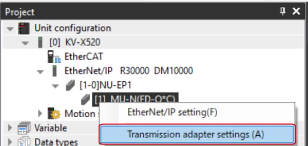
1. Expand the unit configuration in the workspace. Right-click on "Vender Series" and select [Transmission adapter settings (A)].
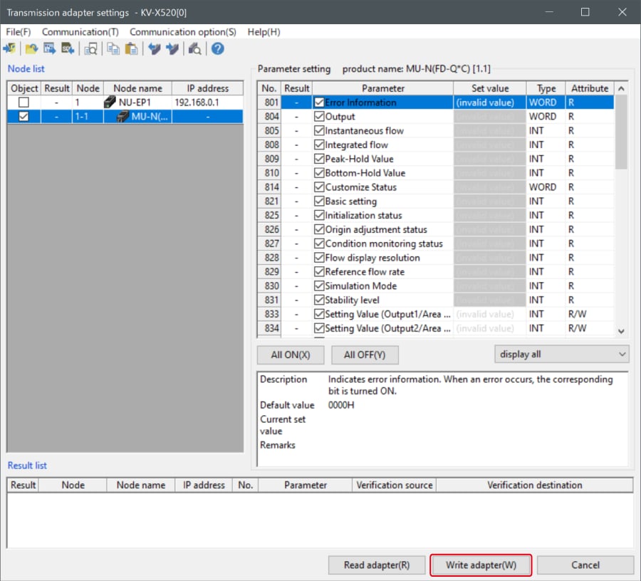
2. Place a check mark in Setting Value for "Vender Series" and enter the setting value.
Click [Write adapter (W)] to write the setting value to the sensor.
*To read the setting value of a sensor, select [Read adapter (R)].
B : Changed from a ladder program
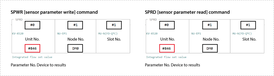
Use message communication to change the setting values from a ladder program.
To perform message communication with KV STUDIO, use the sensor setting commands (SPWR [sensor parameter write] and SPRD [sensor parameter read]).
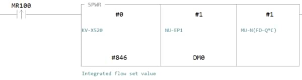
1. In Editor mode, create a ladder program as shown below.
* For the parameter numbers, refer to Parameter list.
2. Transfer the ladder program.
3. When MR100 is turned on, the setting value is changed.
* Store the setting value in DM4 ([Leading device to store results] + 4).
One point
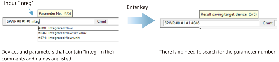
RT (Real-Time) Edit function
When you use a ladder program, you can input device comments or parameter names directly to have input candidates be searched for and displayed automatically.
Extra 1 : Memory Mapping
This section explains the memory mapping for devices used for cyclic communication.
Usable connections
When the GC-1000 is added to the scan list, the following connections are automatically registered.
* Communication load can be reduced by deleting unused connections.
| No. | Connection name | Input/Output | Size (bytes) | RPI (default) | Minimum RPI |
|---|---|---|---|---|---|
| 1 | Communication input / Status data |
Input (GC -> KV)
Output (KV -> GC) |
174 92 |
20 20 |
5 5 |
| 2 | GL-R monitor data (GC-Link port A) | Input (GC -> KV) | 446 | 20 | 10 |
| 3 | GS monitor data (GC-Link port A) | Input (GC -> KV) | 72 | 20 | 10 |
| 4 | GL-R monitor data (GC-Link port B) | Input (GC -> KV) | 446 | 20 | 10 |
| 5 | GS monitor data (GC-Link port B) | Input (GC -> KV) | 72 | 20 | 10 |
Communication input / Status data
Input (GC -> KV)
| Offset | Description | |
|---|---|---|
| 0 | Number of connected units (Expansion unit) | |
| 1 | Number of connected units (Remote I/O module) | |
| 2 | Model information (Main controller) | |
| 3 | Model information (1st expansion unit) | |
| — | — | |
| 12 | Model information (10th expansion unit) | |
| 13 | Model information (1st remote I/O module) | |
| — | — | |
| 16 | Model information (4th remote I/O module) | |
| 17 | Reserved for system | |
| 18 | Operation time | |
| 19 | ||
| 20 | 0 | RUN status (0: STOP / 1: RUN) |
| 1 | Fault status (0: No fault / 1: Fault) | |
| 2 to 15 | Reserved for system | |
| 21 | Error count | |
| 22 | Error code (1st error): Main code | |
| 23 | Error code (1st error): Detail code | |
| — | — | |
| 80 | Error code (30th error): Main code | |
| 81 | Error code (30th error): Detail code | |
| 82 | 0 | Communication output bit 0: 00 |
| — | — | |
| 15 | Communication output bit 0: 15 | |
| — | — | — |
| 85 | 0 | Communication output bit 3: 00 |
| — | — | |
| 15 | Communication output bit 3: 15 | |
| 86 | GC-Link port status | |
Output (KV -> GC)
| Offset | Description | |
|---|---|---|
| 0 | 0 | Communication input bit 0: 00 |
| — | — | |
| 15 | Communication input bit 0: 15 | |
| — | — | |
| 3 | 0 | Communication input bit 3: 00 |
| — | — | |
| 15 | Communication input bit 3: 15 | |
| 4 | Enable code 0: 00 | |
| — | — | |
| 33 | Enable code 1: 13 | |
| 34 | Reserved for system | |
| 35 | Reserved for system | |
| 36 | PLC text | |
| — | ||
| 45 | ||
GL-R monitor data (GC-Link port A)
| Offset | Description | |
|---|---|---|
| 0 | Number of connected units | |
| 1 | Reserved for system | |
| 2 | Main unit type | |
| 3 | Sub unit 1 type | |
| 4 | Sub unit 2 type | |
| 5 | Main unit: No. of optical axes | |
| 6 | Sub unit 1: No. of optical axes | |
| 7 | Sub unit 2: No. of optical axes | |
| 8 | 0 | Switch 1 |
| — | — | |
| 5 | Switch 6 | |
| 6 to 15 | Reserved for system | |
| 9 | Reserved for system | |
| 10 | 0 to 7 | Main unit: Received light intensity (1st optical axis) |
| 8 to 15 | Main unit: Received light intensity (2nd optical axis) | |
| — | — | |
| 73 | 0 to 7 | Main unit: Received light intensity (127th optical axis) |
| 8 to 15 | Reserved for system | |
| 74 | 0 to 7 | Sub unit 1: Received light intensity (1st optical axis) |
| 8 to 15 | Sub unit 1: Received light intensity (2nd optical axis) | |
| — | — | |
| 137 | 0 to 7 | Sub unit 1: Received light intensity (127th optical axis) |
| 8 to 15 | Reserved for system | |
| 138 | 0 to 7 | Sub unit 2: Received light intensity (1st optical axis) |
| 8 to 15 | Sub unit 2: Received light intensity (2nd optical axis) | |
| — | — | |
| 201 | 0 to 7 | Sub unit 2: Received light intensity (127th optical axis) |
| 8 to 15 | Reserved for system | |
| 202 | 0 | 1st optical axis status (0: OFF / 1: ON) |
| — | — | |
| 15 | 16th optical axis status (0: OFF / 1: ON) | |
| — | — | |
| 216 | 0 | 225th optical axis status (0: OFF / 1: ON) |
| — | — | |
| 15 | 240th optical axis status (0: OFF / 1: ON) | |
| 217 | 0 | Error status |
| 1 to 15 | Reserved for system | |
| 218 | 0 | OSSD output status |
| 1 to 15 | Reserved for system | |
| 219 | 0 | Low light intensity alarm: Enabled status |
| 1 to 15 | Reserved for system | |
| 220 | 0 | Low light intensity alarm: Detection status |
| 1 to 15 | Reserved for system | |
| 221 | Low light intensity alarm: Detection threshold | |
| 222 | Low light intensity alarm: Detection time | |
GS monitor data (GC-Link port A)
| Offset | Description | |
|---|---|---|
| 0 | Number of connected units | |
| 1 | 0 | Device information (1st unit) |
| 1 | Lock type information (1st unit) | |
| 2 to 3 | Reserved for system | |
| 4 | Indicator control output (1st unit) | |
| 5 | ||
| 6 | Encoding level settings (1st unit) | |
| 7 to 15 | Reserved for system | |
| — | — | |
| 16 | 0 | Device information (16th unit) |
| 1 | Lock type information (16th unit) | |
| 2 to 3 | Reserved for system | |
| 4 | Indicator control output (16th unit) | |
| 5 | ||
| 6 | Encoding level settings (16th unit) | |
| 7 to 15 | Reserved for system | |
| 17 | 0 | OSSD status |
| 1 | Lock control information | |
| 2 to 15 | Reserved for system | |
| 18 | 0 | 1st unit open/closed status |
| — | — | |
| 15 | 16th unit open/closed status | |
| 19 | 0 | 1st unit lock status |
| — | — | |
| 15 | 16th unit lock status | |
| 20 |
Stores detailed information on the 1st GS unit connected to the GC-Link port A.
bit0: Open/closed status (0: Open / 1: Closed) bit1: Lock status (0: Unlocked / 1: Locked) bit2: Red LED status (0: Off / 1: On) bit3: Green LED status (0: Off / 1: On) |
|
| — | — | |
| 35 |
Stores detailed information on the 16th GS unit connected to the GC-Link port A.
bit0: Open/closed status (0: Open / 1: Closed) bit1: Lock status (0: Unlocked / 1: Locked) bit2: Red LED status (0: Off / 1: On) bit3: Green LED status (0: Off / 1: On) |
|
GL-R monitor data (GC-Link port B)
| Offset | Description | |
|---|---|---|
| 0 | Number of connected units | |
| 1 | Reserved for system | |
| 2 | Main unit type | |
| 3 | Sub unit 1 type | |
| 4 | Sub unit 2 type | |
| 5 | Main unit: No. of optical axes | |
| 6 | Sub unit 1: No. of optical axes | |
| 7 | Sub unit 2: No. of optical axes | |
| 8 | 0 | Switch 1 |
| — | — | |
| 5 | Switch 6 | |
| 6 to 15 | Reserved for system | |
| 9 | Reserved for system | |
| 10 | 0 to 7 | Main unit: Received light intensity (1st optical axis) |
| 8 to 15 | Main unit: Received light intensity (2nd optical axis) | |
| — | — | |
| 73 | 0 to 7 | Main unit: Received light intensity (127th optical axis) |
| 8 to 15 | Reserved for system | |
| 74 | 0 to 7 | Sub unit 1: Received light intensity (1st optical axis) |
| 8 to 15 | Sub unit 1: Received light intensity (2nd optical axis) | |
| — | — | |
| 137 | 0 to 7 | Sub unit 1: Received light intensity (127th optical axis) |
| 8 to 15 | Reserved for system | |
| 138 | 0 to 7 | Sub unit 2: Received light intensity (1st optical axis) |
| 8 to 15 | Sub unit 2: Received light intensity (2nd optical axis) | |
| — | — | |
| 201 | 0 to 7 | Sub unit 2: Received light intensity (127th optical axis) |
| 8 to 15 | Reserved for system | |
| 202 | 0 | 1st optical axis status (0: OFF / 1: ON) |
| — | — | |
| 15 | 16th optical axis status (0: OFF / 1: ON) | |
| — | — | |
| 216 | 0 | 225th optical axis status (0: OFF / 1: ON) |
| — | — | |
| 15 | 240th optical axis status (0: OFF / 1: ON) | |
| 217 | 0 | Error status |
| 1 to 15 | Reserved for system | |
| 218 | 0 | OSSD output status |
| 1 to 15 | Reserved for system | |
| 219 | 0 | Low light intensity alarm: Enabled status |
| 1 to 15 | Reserved for system | |
| 220 | 0 | Low light intensity alarm: Detection status |
| 1 to 15 | Reserved for system | |
| 221 | Low light intensity alarm: Detection threshold | |
| 222 | Low light intensity alarm: Detection time | |
GS monitor data (GC-Link port B)
| Offset | Description | |
|---|---|---|
| 0 | Number of connected units | |
| 1 | 0 | Device information (1st unit) |
| 1 | Lock type information (1st unit) | |
| 2 to 3 | Reserved for system | |
| 4 | Indicator control output (1st unit) | |
| 5 | ||
| 6 | Encoding level settings (1st unit) | |
| 7 to 15 | Reserved for system | |
| — | — | |
| 16 | 0 | Device information (16th unit) |
| 1 | Lock type information (16th unit) | |
| 2 to 3 | Reserved for system | |
| 4 | Indicator control output (16th unit) | |
| 5 | ||
| 6 | Encoding level settings (16th unit) | |
| 7 to 15 | Reserved for system | |
| 17 | 0 | OSSD status |
| 1 | Lock control information | |
| 2 to 15 | Reserved for system | |
| 18 | 0 | 1st unit open/closed status |
| — | — | |
| 15 | 16th unit open/closed status | |
| 19 | 0 | 1st unit lock status |
| — | — | |
| 15 | 16th unit lock status | |
| 20 |
Stores detailed information on the 1st GS unit connected to the GC-Link port B.
bit0: Open/closed status (0: Open / 1: Closed) bit1: Lock status (0: Unlocked / 1: Locked) bit2: Red LED status (0: Off / 1: On) bit3: Green LED status (0: Off / 1: On) |
|
| — | — | |
| 35 |
Stores detailed information on the 16th GS unit connected to the GC-Link port B.
bit0: Open/closed status (0: Open / 1: Closed) bit1: Lock status (0: Unlocked / 1: Locked) bit2: Red LED status (0: Off / 1: On) bit3: Green LED status (0: Off / 1: On) |
|
