
Wide Area CMM
WM-6000 series
Features Wide Area CMM WM-6000 series
Software Intuitive Software for a Minimal Learning Curve
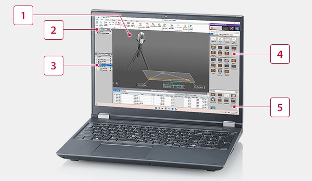
Conventional CMM software can be difficult to use, meaning measurements take too long to perform. The WM-6000’s software includes a variety of images and illustrations for immediate operation regardless of the operator’s experience level.
-
1Measurement results display
-
2Scanning object tree
-
3Sortable elements tree:
Measured elements can be vertically rearranged by dragging them up or down. -
4Measurement menu
-
5Favorites menu
Diverse Measurement Capabilities
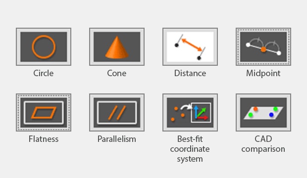
Simple measurement menu:
In addition to distance, angle, holes, and other basic measurements, complex measurements are made easy, including virtual center-lines, GD&T measurements such as flatness, XYZ coordinate measurements, and CAD comparisons.
Accurate Measurement Even with Temperature Changes
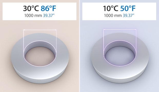
Temperature Compensation function:
The Temperature Compensation function ensures measurement is performed under the same standards, just like a climate-controlled measuring room, even if the ambient temperature is not constant. Simply select the current temperature and the material, and the WM-6000 will automatically compensate for the standard temperature dimensions.
Fast Post-Measurement Pass/Fail Judgment
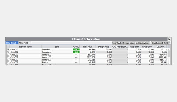
Design value/tolerance input:
Enter design values and tolerances to automatically judge the measurement (determine the OK/NG result), ensuring measured values are properly checked. Design values and tolerances can also be automatically applied by importing CAD data.
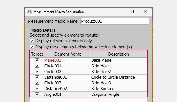
Save Measurement Procedures
Macro Registration function:
Frequently used measurement procedures can be registered as macros and saved in the application. Saved macros can then be used whenever needed, ensuring efficient measurement with the same procedure.
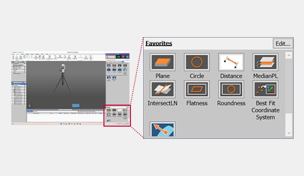
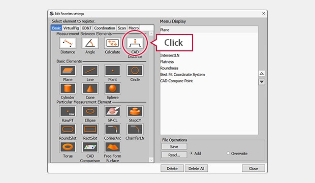
NEW Frequently Used Menu Registration
Favorites Menu:
Registering menu items to the Favorites Menu makes selecting the desired item even faster. Measuring only those items used in-house also eliminates the need to worry about confusing new users. Simply click and select a frequently used menu item to display it in the lower-right corner of the screen.
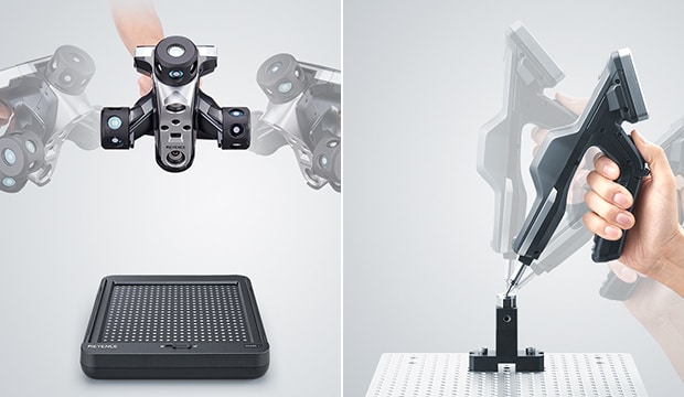
Measurement Linking Improved Usability with Contact and Scanning Measurement Linking
With two probes available — a contact probe and a laser-scanning probe—both dimensional measurements and shape measurements are easy for all users. Simply swap between probes and continue measuring, with no complicated settings required.
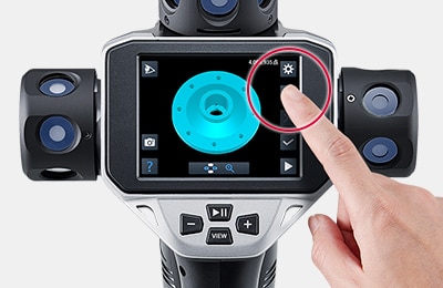
Contact Probe Contact-Based Coordinate Creation and Dimensional Measurement
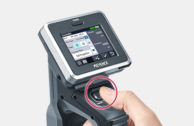
3-step measurement with no need for a PC:
The probe’s built-in touch screen can be used to select measurement elements, perform measurement, and check measurement results.
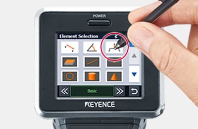
1. Select an element
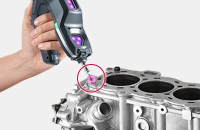
2. Touch the part with the probe
3. Measure
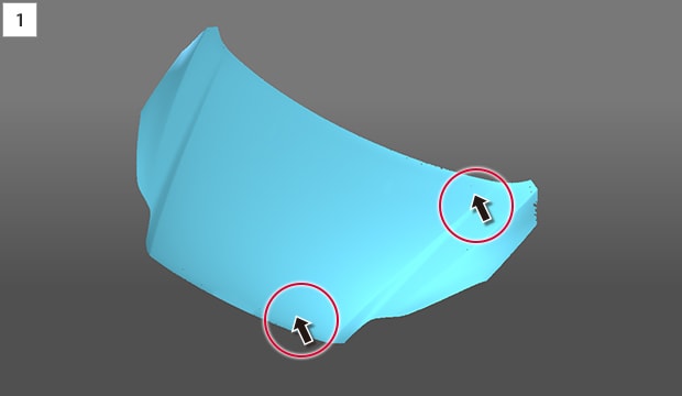
Laser-Scanning Probe Scanning and Shape Measurement Over a Wide Area
3-step scanning and data checking:
The probe’s built-in touch screen can be used to start a scan, check the scan status, and combine scanned data (create a mesh) without a PC.
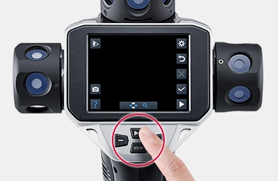
1. Press the scan start button
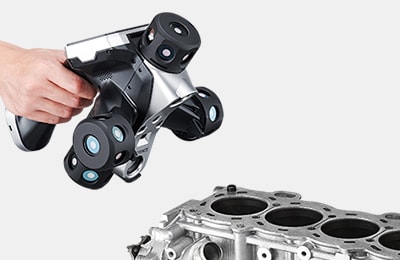
2. Scan with the probe
3. Create a mesh with the built-in touch screen
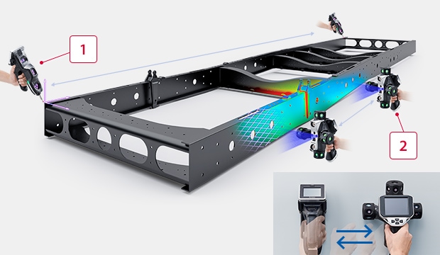
Easy Probe Switching
Switching probes is as simple as putting one probe down and picking the other up, ensuring easy usability for all users.
-
1Intuitive contact based usability
-
2Simply wave the probe across the target area
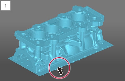
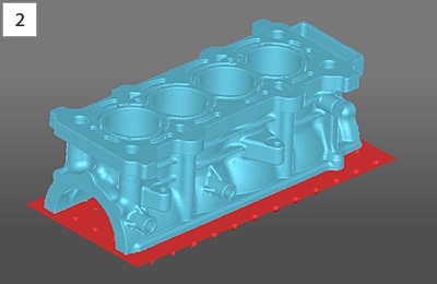
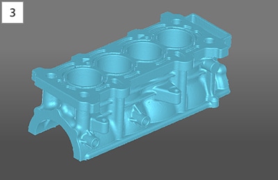
CAD 3D CAD Data Comparison for More Diverse Applications
Compare surface variation between the target and an imported 3D CAD model. Measured elements can also be output in various formats, including STEP.
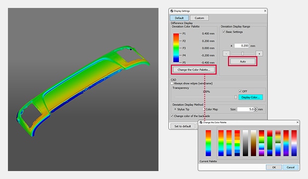
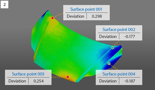
Areas higher than the CAD data are shown in red, and lower areas are shown in blue.
Differential Color Maps for Quick Comparisons
The color map makes it easy to visualize differences between the target and the imported 3D CAD data, allowing for easy and quick confirmation of trends in relation to product design values. Color map settings can also be adjusted to suit the application.
NEW Point-to-Click Surface Point Measurement
Measuring a desired point is intuitive. Simply click the target location to compare it with the 3D CAD data. Target coordinate lists can also be imported to check and measure several locations all at once.
Simply click a location for measurement.
Output data can be checked and edited with various external software.
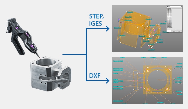
3D CAD Data Export
Elements measured with the contact probe and those created based on scanned data can be output as 3D CAD data in STEP or IGES format, or as 2D data in DXF format. Scanned data can also be output as STL and Point cloud format.
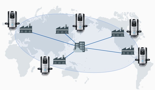
Install the offline application software to a PC to share data among relevant parties for improved efficiency.
Remotely Access Data Anywhere
The offline application can be used to create inspection routines and check measurement results on a different PC without having to connect the camera. This makes it possible to perform, check, and edit measurements without needing the equipment at hand.
Usage examples:
- Creating inspection routines from the CAD model to increase machine uptime
- Sharing measurement data with other sites and overseas factories
- Capturing data on-site and measuring later on at the office
New Functions New Functions Made Possible with the Laser-Scanning Probe
A wide variety of new functions are available, including dimensional and geometric measurement using scanned data, cross-sectional measurements at any location, and surface condition analysis using the texture camera.
NEW Cross-Sectional Measurement with No Cutting Required
Non-destructive cross-sections can be created even for areas that are conventionally difficult to measure, allowing for detailed measurement and analysis without having to cut the product. Users can also use 3D CAD data to set base planes and measure cross-sections from any angle.
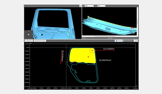
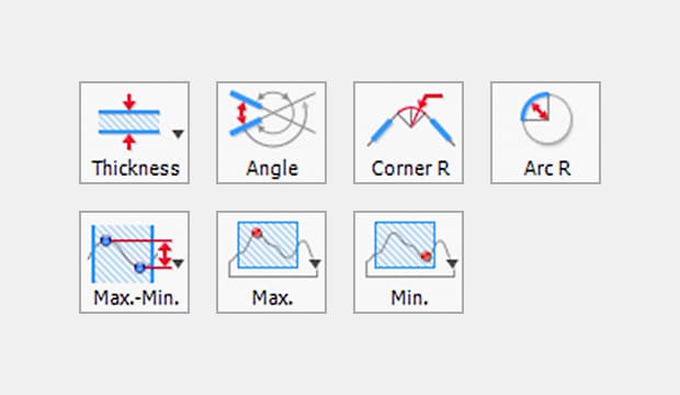
Various menu options specifically for cross-sectional measurement, including thickness and cross-sectional length, are available.
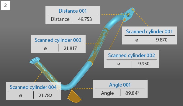
NEW Element-Based Measurements
Scanned data can be used to create a variety of elements, including planes and cylinders. The data can also be used for 3D measurements such as distance and flatness.
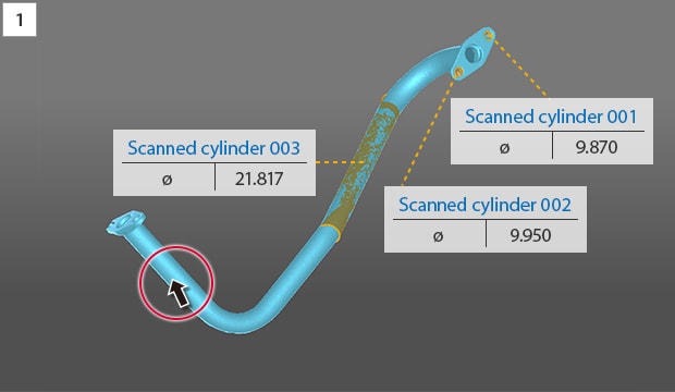
Simply click the area to measure.
NEW Texture Function for Saving Surface Conditions
Texture information can be overlaid onto scanned data. Product inspection results and any additional notes can be saved for later use.
Before texture overlay
After texture overlay
NEW Unnecessary Data Removal with Just a Click
With conventional methods, removing unnecessary entries in scanned data can be extremely time-consuming.
The WM-6000 makes deleting unneeded data fast and easy for all users.
Click the unnecessary data.
Remove.
Usable in Any Process, from Material Preparation to Assembly
From material cutting, post-welding dimensioning/form measurement, shop floor checks, in-process measurement cutting, post-assembly positioning, measurement in any environment, and maintenance, repair, and overhaul (MRO), to defect analysis.

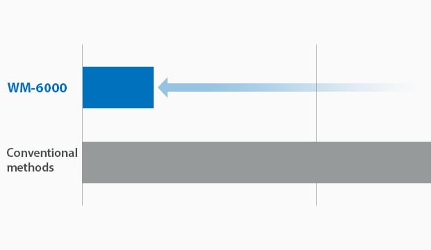
Significant time savings
Comparison of Measurement Time Required
The WM-6000 can be used easily by anyone in a wide variety of applications, enabling single-person measurement for targets that would otherwise take a lot of time or more workers with conventional methods.
Other Applications Various Useful Features for the Manufacturing Industry
Support Machine Installation and Alignment
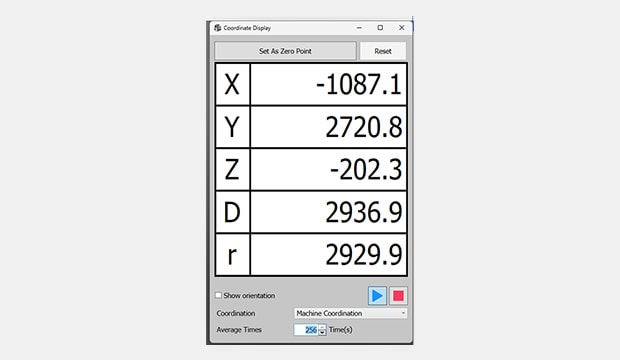
Real-Time Coordinates function:
The Real-Time Coordinates function provides XYZ coordinates for the probe’s current position. This function is useful when installing and adjusting manufacturing equipment.

Built-in touch screen
Simplifying Second and Subsequent Inspections:
Run Mode function:
Image data from measured targets can be saved as work instructions for FAIs or repeated inspection. These procedures can be used for pass/fail judgment when measuring multiple targets of the same shape. Simply follow the on-screen instructions and touch the probe to the highlighted points on the target.
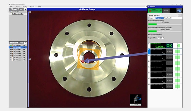
Guided measurement window
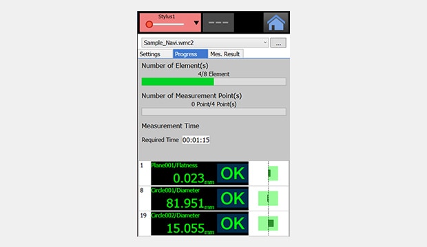
Tolerance judgment screen following measurement
Automatic Report Creation
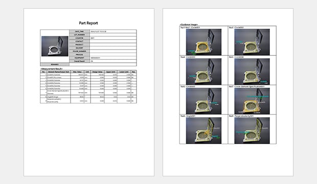
Inspection report with images:
Measured data can be automatically converted into inspection reports. This ensures information is not omitted and prevents transcription errors. Reports are output in rich text format (RTF) so users can flexibly edit them as needed. Reports can also be printed in PDF format for easy sharing.
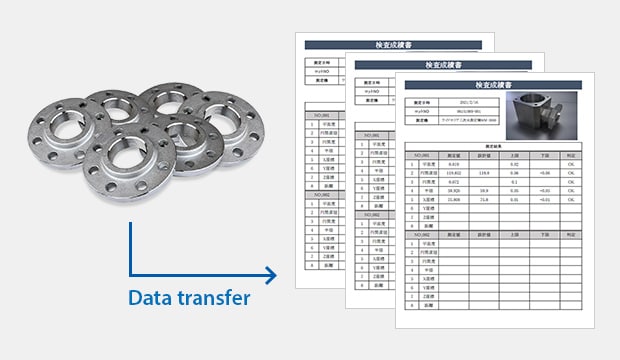
Data transfer
Destination-Specific Inspection Report Formats*1
Data Transfer function:
This function takes data measured by the WM-6000 and transfers it to a custom Excel*2 sheet. Data transfer settings can be configured directly from the PC without the WM connected.
*1 WM-H3T
*2 Excel is either a registered trademark or trademark of Microsoft Corporation in the United States and/or other countries.
Automatic Data Summarization: Statistical Analysis Function
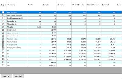
Verification of statistical values
Key statistics values such as the pass/fail count, max. value, min. value, average, σ, 3σ, 6σ, and Cpk for selected measurement items can be calculated automatically and displayed.
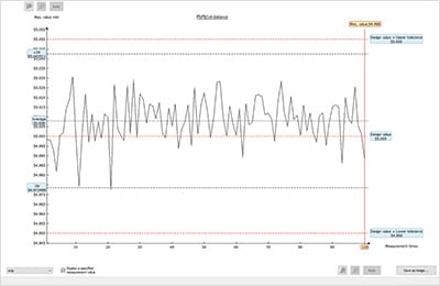
Trend graph
With the WM-6000, the trends for selected measurement items can be viewed in a graph. This allows for visualization of upward/downward trends of product dimensions, periodic fluctuations, and increased variation.
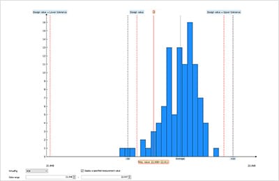
Histogram
The distribution for each selected measurement item can be viewed in a graph. The graph shows the range of measurements as the horizontal axis and frequency as the vertical axis, allowing users to see whether the measurements are centering on any values in particular and how the measurements vary.
Support System
Easy Probe Calibration
Calibrating the probe is incredibly easy with no difficult operations required. Calibration data can also be stored on the device, eliminating the need to save new data each time.
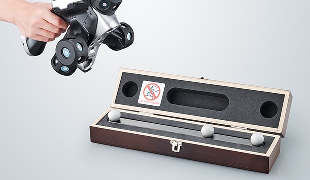
Dedicated Ball Gauge for Quick Daily Certification*1
Users can verify measurements daily using the dedicated ball gauge.
*1 Optional: WM-SG
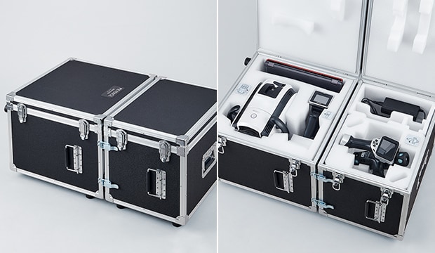
No Calibration Down-Time
While typically not required, if service or calibration are needed, simply place the probe and camera unit in the dedicated case and send them to KEYENCE. We will lend you a temporary replacement unit free of charge while your machine is being serviced.
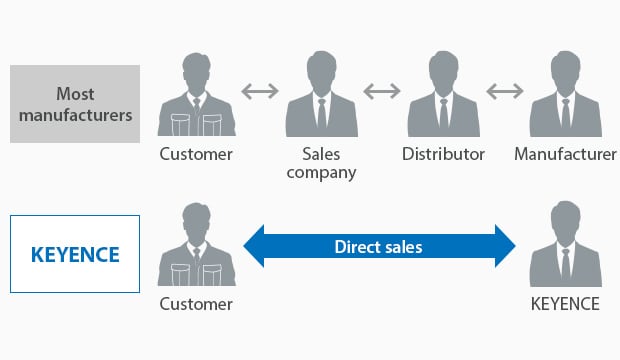
Direct-Sales Advantage
Due to our direct-sales system, our sales engineers, who have a wealth of specialized knowledge, support our customers directly, so we can handle our customers’ issues in a timely manner.

Delivery
Products are delivered to customers via an express delivery service. Each product has a vibration-resistant structure.

On-Site Training
Dedicated KEYENCE staff will install and explain how to operate the product.

Technical Support
Dedicated CMM staff are on-call at KEYENCE’s sales office to respond to customer inquiries.
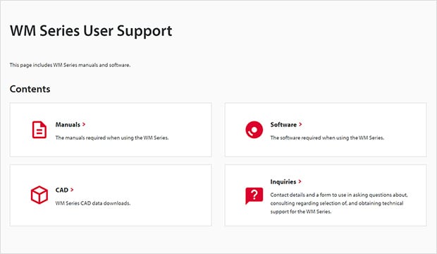
Dedicated Support Site for Improving Usability
KEYENCE offers a user support site accessible only to users of its products. This site includes a variety of easily accessible information such as manuals and software updates.
