2D/3D Laser Profiler
LJ-X8000 series
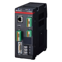
Raw data output controller LJ-X8000A

*Please note that accessories depicted in the image are for illustrative purposes only and may not be included with the product.
Specifications
Model | LJ-X8000A | |||
Head input | Up to 1 head | |||
Sampling cycle (trigger interval) | When connecting the LJ-X8000 Series: maximum speed of 16 kHz (63 μs) *1 | |||
Interface | Control input | Supports the batch measurement start (MEASURE_START) and batch measurement stop (MEASURE_STOP). | ||
Control output | •Supports the trigger ready (READY) and system error (ERROR). | |||
Synchronous input / output | For trigger synchronization of multiple controllers*5 | |||
Ethernet | Supports the profile output, setting, controll, 1000BASE-T/100BASE-TX*6 | |||
Encoder input | One system | |||
Response frequency | RS-422 | Single phase/Z-phase : 1.6 MHz | ||
Open collector (OC) | Single phase/Z-phase : 100 kHz | |||
Laser ON input | Non-voltage Input (a short circuit via the short pin at the time of shipment from the factory) | |||
Ratings | Power voltage | 24 VDC±10% | ||
Maximum current consumption | 1.3A | |||
Environmental resistance | Ambient temperature | 0 to + 45 °C (DIN rail mounting) / 0 to + 40 °C (side mounting) | ||
Relative humidity | 85% RH or less (no condensation) | |||
Weight | Approx. 700 g | |||
*1 When the measurement range is narrowed in accordance with the binning settings. | ||||


