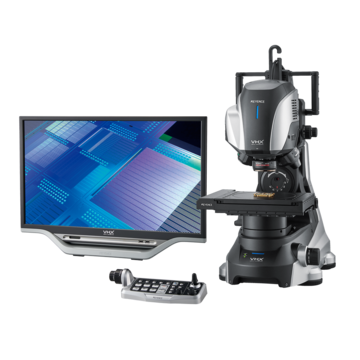
Digital Microscopes
Observation and Measurement of Hydraulic Components Using Digital Microscopes
Hydraulic components are used for equipment in which a small force needs to be converted into a large force, such as building machinery including excavators and automobile brakes. Hydraulic components have high energy density, which allows devices to be smaller and lighter. This section introduces observation and measurement examples of hydraulic components using digital microscopes.
Principle of Hydraulic Mechanism
If pressure is exerted on part of a stationary fluid (oil) in an enclosed container, this pressure will be distributed evenly and vertically to all surfaces the fluid contacts, regardless of the shape of the container. This phenomenon is called Pascal's law. Hydraulic systems use oil to amplify force based on this principle.
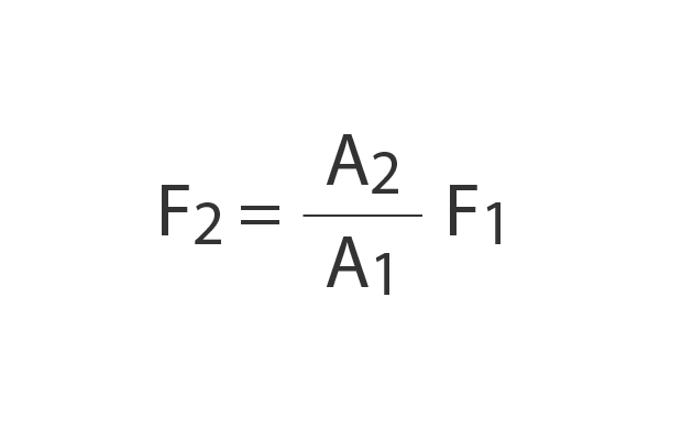
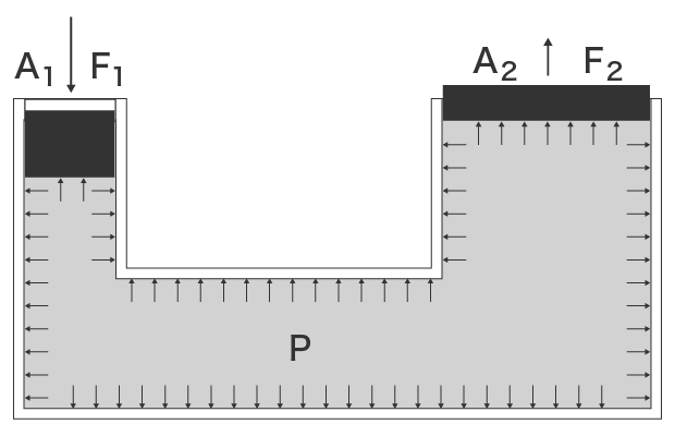
A1: Sectional area A1 F1: Force F1
A2: Sectional area A2 F2: Force F2 P: Pressure
Get detailed information on our products by downloading our catalog.
View Catalog

Advantages and Disadvantages of the Hydraulic Mechanism
The hydraulic mechanism has great advantages but also presents some unique disadvantages.
Advantages of the hydraulic mechanism
- Great power can be transmitted accurately at high speed.
- Power density is high, allowing devices to be smaller and lighter.
- Pressure control valves ensure a high level of safety.
- Service lives are long due to oil lubrication.
Disadvantages of the hydraulic mechanism
- Susceptible to contamination by oil.
- Oil may ignite. (Ignition point is 200 to 250°C (392°F to 482°F).)
- Oil may leak.

Typical Hydraulic Components
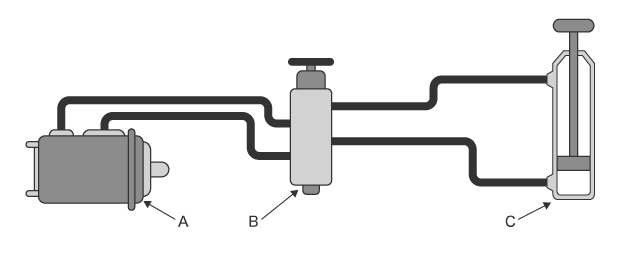
A: Hydraulic pump B: Control valve C: Hydraulic actuator
- Hydraulic pump
Hydraulic pumps use electric motors or engines as a power source to apply pressure to hydraulic oil. - Control valve
Control valves control the pressure, flow rate, and flow direction of hydraulic oil. These valves are respectively called pressure control valves, flow rate control valves, and directional control valves. - Hydraulic actuator
Hydraulic actuators convert fluid power into mechanical power. Hydraulic actuators include hydraulic cylinders which convert fluid power into linear motion, hydraulic motors which convert fluid power into rotary motion, and oscillating actuators which convert fluid power into oscillating motion.
Observation and Measurement Examples of Hydraulic Components Using Digital Microscopes
These are the latest examples of observation and measurement of hydraulic components using KEYENCE’s VHX Series 4K Digital Microscope.
Observation of scratches on a hydraulic shaft
Optical Shadow Effect Mode makes it possible to visualize the order that scratches were made and the depth of each scratch.
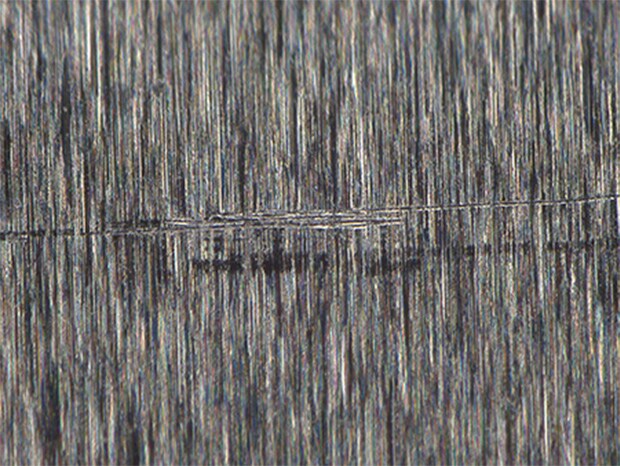
VHX-E100, 400×, ring illumination, normal image
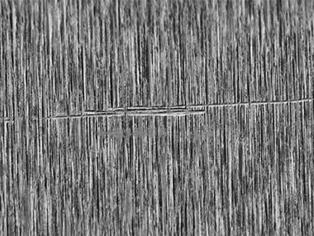
Optical Shadow Effect Mode image
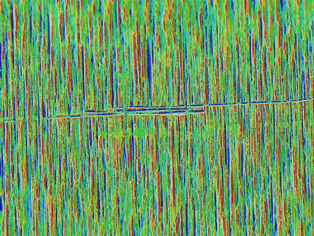
Color Map image
Observation of a hydraulic part internal wall
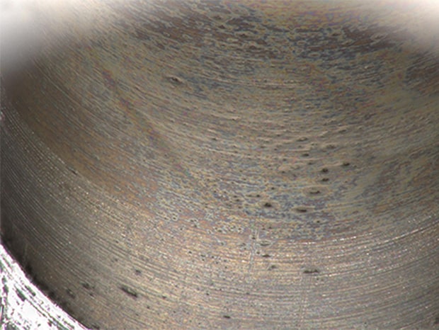
VH-Z20, 200×, ring illumination
Using the depth composition function for tilted observation allows for non-destructive observation of internal walls.
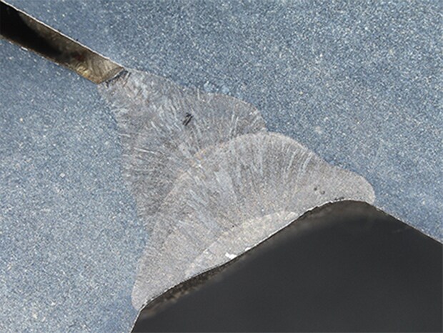
Observation of the welded cross-section of a hydraulic part

VHX-E20, 20×, ring illumination
Welding boundaries can be clearly observed at 4K-resolution.
Observation of flaws on internal walls of a hydraulic valve
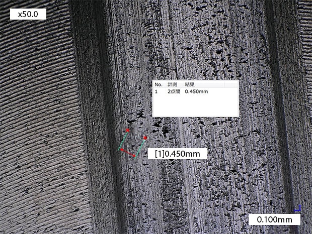
VH-Z00, 50×, ring illumination
Flaw sizes can be quantified using the 2D measurement function.
Profile measurement of a construction machine hydraulic part
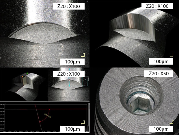
VH-Z20, 100×, ring illumination
Profiles used to be measured after destruction, but now can be measured without destruction.
Defect analysis of a casted hydraulic part surface
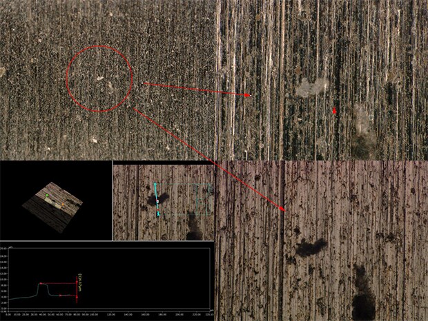
ZS-200, 1500×, coaxial illumination
Even areas that cannot be measured with profilometers can be analyzed in 3D with no contact.
Roughness measurement of a construction machine hydraulic part
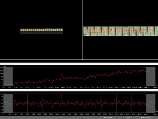
VHX-E500, 700×, coaxial illumination
Roughness data can now be accumulated in a database.
Get detailed information on our products by downloading our catalog.
View Catalog