Digital Microscopes
Observation and Measurement of Coating Using a Digital Microscope
The process of adding new functionality to relatively thin base materials (targets) such as films, sheets, steel plates, or glass is also called “converting.” In general, this is done through coating actions such as chemical agent coating, deposition, and sputtering. Functionalization is used in a wide range of fields, such as for touch panel electrodes for smartphones and tablets, thin film coating on LCD glass, and precision pattern coating on electronic PCBs. This section introduces coating observation and measurement examples using a digital microscope.
Difference between plating and coating
- Plating
Electroplating is when a conductive metal surface is coated with a different material. This is perhaps the most common method for coating a material with metal. Other methods include chemical plating, which uses chemical reactions; molten plating, which uses immersion in molten metal; and vapor deposition plating, which uses a metal vapor spray. - Coating
Coating makes it possible to create a film layer on both conductive and non-conductive surfaces. Plating can also be thought of as one coating type.
Get detailed information on our products by downloading our catalog.
View Catalog

Purposes of coating
- Functionalization
Coating can be used to increase the functionality of a base material (target) such as by improving adhesion, wettability, water repellency, corrosion resistance, heat resistance, and wear resistance. - Surface processing
Surface processing is used to optimize the surface of a base material by coating it with a chemical agent. One example is the hydrophobic treatment of semiconductor wafers using a chemical agent before the resist coating process. - Decoration (design)
Coating is often used to improve the appearance (design) of a target.
We’re here to provide you with more details.
Reach out today!

Coating types
- Dry coating
Dry coating is a generic term for the technique that coats a "solid" material for functionalization of the base material. Typical coating methods include vacuum deposition, ion plating, and sputtering. Dry coating is used for coating metal materials and allows high-quality deposition without the need for a drying process. The disadvantages are the larger size of equipment, limitations on continuous production, and higher costs. - Wet coating
The wet coating technique is commonly used in a wide range of industrial fields. The material for functionalization is "liquefied" through the process of dissolving or dispersion into a medium. The liquefied material is uniformly applied to the base material and then dried or cured to be converted into a solid film. When it is necessary to avoid adhesion of dust or foreign particles onto the liquid film, wet coating is performed in a clean room. Unlike dry coating, this method does not require a vacuum environment but instead can be done in an atmospheric environment. A wide selection of equipment is available, and the target (base material) can be fed continuously.
Because wet coating provides numerous advantages in high-volume production, it has been adopted widely in various coating systems.
We’re here to provide you with more details.
Reach out today!

Coating observation/measurement examples using a digital microscope
The latest examples of coating observation and measurement using KEYENCE’s VHX Series 4K Digital Microscope are introduced below.
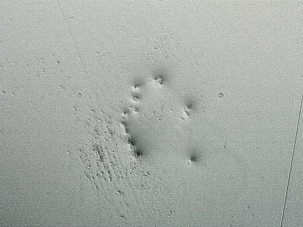
Observation of defects on resin-coated surfaces

ZS-200, 1000×, ring illumination image
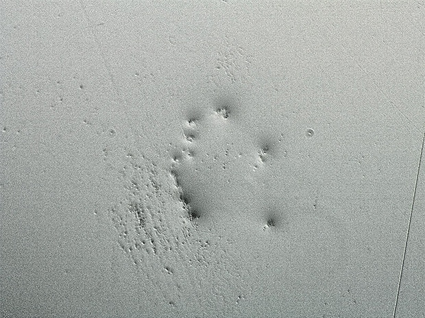
Coaxial illumination + HDR image
HDR allows for visualization of defects.
Observation of coating material
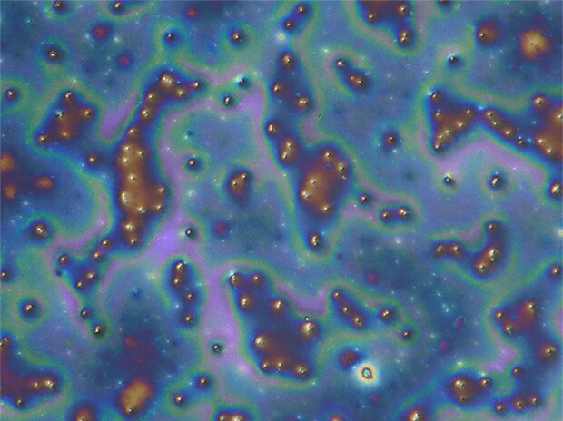
VHX-E500, 2000×, coaxial illumination image
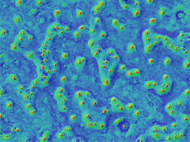
Optical Shadow Effect Mode (color mapping) image
Optical Shadow Effect Mode allows for visualization of surface irregularities.
Observation of uneven applications of coating
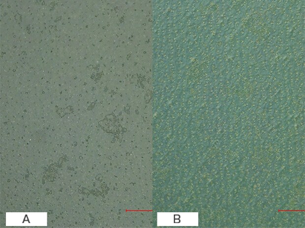
VH-Z20, 200×, coaxial illumination
A : Normal image B : Differential Interference Contrast (DIC) + HDR image
Differential Interference Contrast (DIC) and HDR allow for visualization of uneven applications.
Transparent coating depth composition
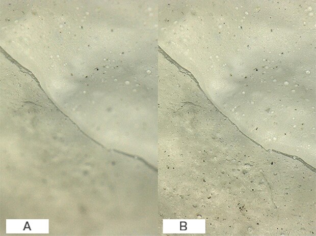
VH-Z20, 100×, ring illumination
A : Normal image B : Depth composition image
Observation of transparent coating is also possible.
Observation of coating on rubber products
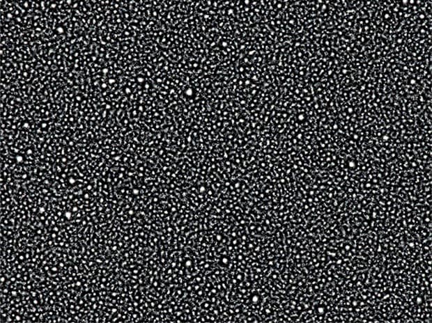
VHX-E500, 1500×, coaxial illumination + HDR image
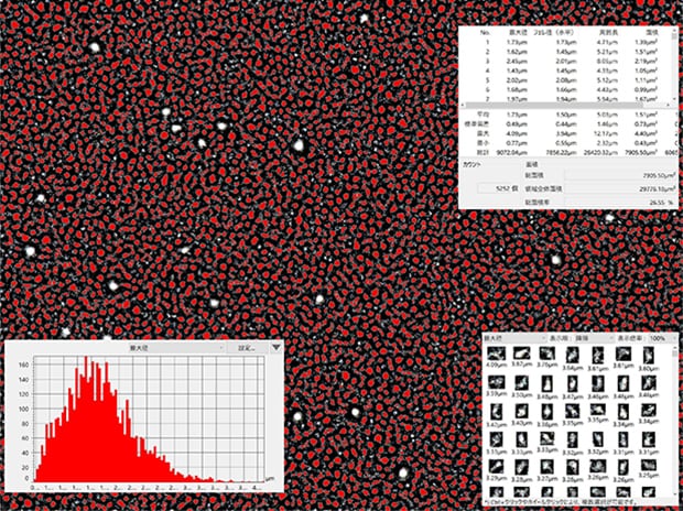
Automatic area measurement image
Automatic area measurement allows for quantification of coating particle variations.
Measurement of difference in thicknesses of wafer coating
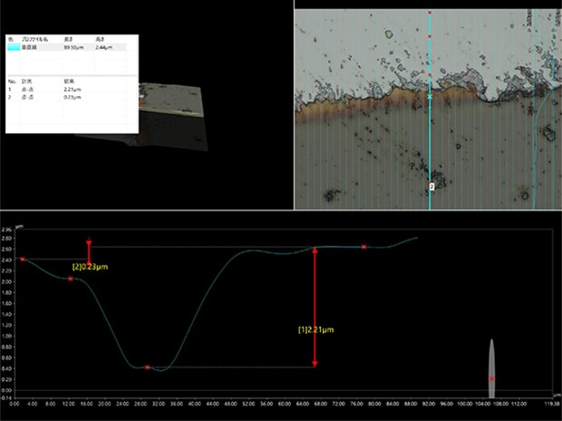
VHX-E2500, 2500×, coaxial illumination
Packaged PCB coating thickness measurement
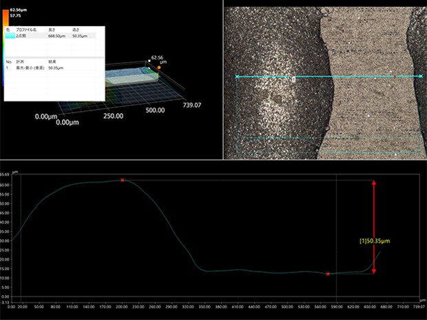
VH-Z100, 400×, coaxial partial illumination
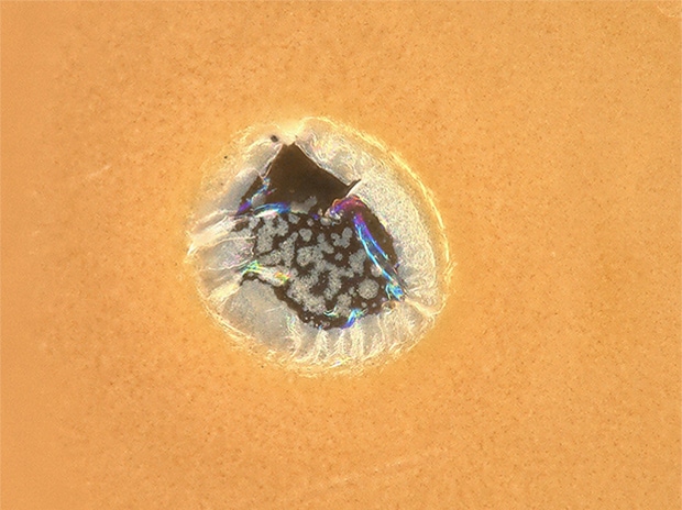
VHX-E500, 700×, coaxial illumination + Polarizing filter
Observation of foreign particles on transparent coating
Foreign particles were confirmed inside the coating material.
Get detailed information on our products by downloading our catalog.
View Catalog


