Digital Fiber Optic Sensor

FS-N40 series

Catalogs View Catalog

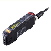
Main Unit (M8 Connector Type) FS-N41C

FS-N41C - Main Unit (M8 Connector Type)

*Please note that accessories depicted in the image are for illustrative purposes only and may not be included with the product.

Data Sheet (PDF)

Manuals

CAD Data

360°view (3D PDF)

Software

  • CE Marking
  • UL Listing(c/us)

Specifications

Model

FS-N41C*1

Type

M8 Connector*2

Main unit/expansion unit

Main unit

Response time

23 µs (S-HSPD*3) /50 µs (HSPD*4) /250 µs (FINE) /500 µs (TURBO) /1 ms (SUPER) /4 ms (ULTRA) /16 ms (MEGA) /64 ms (TERA)

Number of control outputs

2*5

Number of external inputs

1*5

Light source LED

Transmitter side: Red, four-element LED (wavelength: 660 nm)

Control output

Open-collector, 30 V or less 100 mA or less per output,
100 mA or less total for 2 outputs (when used as a solitary unit) /20 mA or less (when used as an expansion unit)
Residual voltage
NPN 1.4 V or less (output current: 10 mA or less) /2 V or less (output current: 10 to 100 mA)
PNP 1.6 V or less (output current: 10 mA or less) /2.2 V or less (output current: 10 to 100 mA)

External input

Input time: 2 ms (ON) /20 ms (OFF) or longer*6

Protection circuit

Protection against reverse power connection, output overcurrent, output surge, and reverse output connection

Mutual interference prevention

S-HSPD/HSPD: 0 units, FINE: 4 units, TURBO/SUPER/ULTRA/MEGA/TERA: 8 units (The mutual interference prevention values are twice those shown here when Double is set.)

Power supply

Power voltage

10 to 30 VDC (including 10 % ripple (P-P) or less) , class 2 or LPS*7

Power consumption

During normal operation: 910 mW or less (36 mA or less at 24 V/65 mA or less at 12 V)
ECO ON: 840 mW or less (33 mA or less at 24 V/60 mA or less at 12 V)
ECO FULL: 750 mW or less (30 mA or less at 24 V/52 mA or less at 12 V)*8

Environmental resistance

Ambient light

Incandescent lamp: 20,000 lx or less, sunlight: 30,000 lx or less

Ambient temperature

-20 °C -4 °F to +55 °C +131 °F (no freezing)*9

Vibration resistance

10 to 55 Hz; double amplitude 1.5 mm 0.06"; 2 hours each for X, Y, and Z axes

Shock resistance

500 m/s2; 3 times each for X, Y, and Z axes

Case material

Main unit and cover: polycarbonate

Weight

Approx. 25 g

*1 IO-Link Specifi cation V.1.1/COM2 (38.4 kbps) is supported.
*2 Ensure the cable length is 30 m 98.4" or less for the M8 connector type. Ensure the cable length is 20 meters 65.6' or less when connecting by way of IO-Link.
*3 Restrictions when S-HSPD is selected
Output 2 of dual output types is fixed to OFF.
IO-Link communication cannot be used.
Area detection, Area % Mode, DATUM, Rising edge, and Falling edge cannot be selected for Detection Mode.
Output timer, Limit Detection, and Display Gain cannot be used.
FULL cannot be selected for the ECO function.
*4 Restrictions when HSPD is selected
Display Gain cannot be used.
*5 Output 2 and the external input are selectable.
*6 The input time becomes 25 ms (ON)/25 ms (OFF) when external calibration input is selected.
*7 When expanding the system to 9 or more units, use a power supply voltage of 12 V or higher.
*8 The load current is excluded. The power consumption including the load when the maximum number of units are connected is 38 W max.
*9 When expanded by 1 to 2 units: -20°C -4°F to +55°C +131°F. When expanded by 3 to 10 units: -20°C -4°F to +50°C +122°F.
When expanded by 11 to 16 units: -20°C -4°F to +45°C +113°F. When using 2 outputs, 1 unit is counted as 2 units.
The prescribed values for the ambient temperature assume that the sensor amplifi er has been mounted on a DIN rail installed on a metal surface.
Exercise special care when installing the product in an airtight space.

Data Sheet (PDF) Other Models