
AC Servo Systems
SV2 series
Three-phase or single phase AC200 to 240V For 750W SV2-075L2
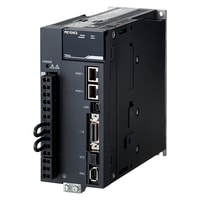
*Please note that accessories depicted in the image are for illustrative purposes only and may not be included with the product.
Specifications
Model | SV2-075L2 | |||
General specifications | Capacity | 750 W | ||
Input power supply | Voltage/frequency | Main circuit | 3-phase (or single phase) 200 to 240 VAC +10 to -15%, 50/60 Hz | |
Control circuit | Single-phase 200 to 240 VAC +10 to -15%, 50/60 Hz | |||
Allowable frequency fluctuation | Main circuit/control circuit | No more than ±5% | ||
Overvoltage category | III | |||
Control mode | Three-phase full-wave rectification, IGBT, PWM control, sine-wave current driving method | |||
Feedback | 22-bit serial encoder (absolute) communication, | |||
Operating environment | Operating atmosphere | Enclosure rating | IP20 | |
Pollution degree | Pollution degree: 2 (in an IP54 or higher control panel) | |||
Operating ambient temperature | -5 to +60°C 23 to 140°F (no freezing; reduced ratings at +55°C 131°F or more) | |||
Storage ambient temperature | -20 to +85°C -4 to +185°F (no freezing) | |||
Operating/storage ambient temperature | 95% RH or less (no condensation) | |||
Altitude | 2000 m 6561.7' or less above sea level (usable at reduced ratings at 1000 m 3280.8' or more) | |||
Vibration resistance | 4.9 m/s2 16.1'/s2 (JIS C60068-2-6 compliant) | |||
Impact resistance | 19.6 m/s2 64.3'/s2 ( JIS C60068-2-27 compliant) | |||
Other | No static electricity noise, strong electric fields, magnetic fields, or radiation present | |||
Min. insulation resistance | 500 VDC, 1 MΩ or more with insulation resistance tester | |||
Applied standard | UL/CSA standards | UL61800-5-1, CSA22.2 No.274 | ||
CE marking | Low-voltage directive | EN61800-5-1, EN50178 | ||
EMI | EN55011 Class A, EN61800-3, EN61000-6-4 | |||
EMS | EN61800-3, EN61000-6-2 | |||
North America EMI standard | FCC Part15 B, ICES-003. Class A | |||
Structure | Type | Attached to base mount | ||
Safety function | STO function (STO/EN61800-5-2) | |||
Safety function | Safety parameters | SIL3/EN61508, SIL CL 3/EN62061, | ||
Response time | 8 ms (max.) | |||
Input | STO1, STO2: Base block signal for power module | |||
Output | EDM: Built-in safety circuit status monitoring (fixed output) | |||
Applied standard | EN61800-5-2, EN ISO13849-1: 2008, EN61508, EN62061, EN60204-1, EN61326-3-1 | |||
Protection function | Overcurrent, overvoltage, undervoltage, overload, regenerative abnormalities, etc. | |||
Insulation withstand voltage | 1500 VAC or more (between primary side and ground) | |||
Weight | Approx. 1.6 kg | |||
Power supply/current capacity and power loss | Main circuit power supply | Three-phase 200 V/Single phase 200 V | ||
Max. applicable motor capacity | 750 W | |||
Power supply capacity for 1 amplifier | Three-phase 200 V: 1.6 kVA, Single phase 200 V: 1.9 kVA | |||
Output current | Continuous | 5.5 Arms | ||
Max. | 16.9 Arms | |||
Main circuit power loss | 43.8 W | |||
Regenerative resistor power loss | 8 W | |||
Control circuit power loss | 17 W | |||
Total power loss | 68.8 W | |||
Rated input current | Main circuit | Three-phase 200 V: 4.1 Arms, Single phase 200 V: 8.7 Arms | ||
Control circuit | 0.2 Arms | |||
Rush current | Main circuit | 34 A | ||
Control circuit | ||||
Performance specifications | Performance | Speed control range | 1:5000 (load torque ≤ rated torque conditions) | |
Speed fluctuation rate | At load fluctuation | ±0.01% or less with load fluctuations of 0 to 100% (at rated rotation speed) | ||
At main circuit voltage change | 0% with ±10% of rated voltage (at rated rotation speed) | |||
At ambient temperature change | ±0.1% or less with ambient temperatures of 0 to +50°C 32 to 122°F (at rated rotation speed) | |||
Torque control accuracy (reproducibility) | ±1% | |||
Speed frequency response frequency | 2.6 kHz | |||
Dynamic brake | Operated at main circuit power supply OFF, servo alarm, limit switch detection (LSP/LSN), forced stop detection (FSTOP) | |||
Regenerative resistor | Built-in regenerative resistor: 50 W to 400 W ... not installed | |||
Display Function | Panel function | 7-segment LED | ||
Status display LED | CHARGE: For notification of main circuit power supply input (orange) | |||
Auxiliary function | Gain control, alarm history, Z-phase search, etc. | |||
I/O specifications | Sequence input signal | Number of inputs | 7 (3 high-speed input, 4 general input) | |
Max. input voltage | 28.8 VDC | |||
Rated input voltage | 24 VDC | |||
Min. ON voltage | 19 VDC | |||
Min. OFF current/voltage | High-speed input: 0.6 mA, general input: 0.3 mA | |||
Common point mode | 7 points/1 common point (1 terminal) (bidirectional) | |||
Input time constant | 250 μs, 500 μs, 1 ms, 2.5 ms, 5 ms, 10 ms | |||
Input current | High-speed input: 4.5 mA, general input: 3.7 mA | |||
Input impedance | Approx. 4.7 kΩ | |||
Assignable input signals | Full signal assignment, logic-settable forced stop (FSTOP), | |||
Sequence output signal | Number of outputs | 4 | ||
Output mode | Transistor NPN output | |||
Rated load | 30 VDC / 50 mA | |||
Leakage current when OFF | 0.1 mA | |||
Residual voltage when ON | 1.5 VDC or less | |||
Common point mode | Independent common | |||
Assignable output signals | Individual signal assignment excluding ALARM signal, logic-settable alarm (ALARM), | |||
Analog Feedback Input signal monitor | Max. input voltage | ±12 V | ||
Accuracy | ±1% of F.S. | |||
Resolution | ±10 bits | |||
Input impedance | 30 kΩ | |||
Encoder division pulse output signal | Output mode | Phase A (A+/A−), phase B(B+/B−), phase Z (Z+/Z−): Differential line-driver output | ||
Line driver | SN75ALS174 (T.I.) or equivalent | |||
Output frequency | 1.6 Mbps (with 2-phase, 4 times multiplication, 6.4 MHz or equivalent) *3 | |||
Analog monitor output | No. of channels | 2 ch | ||
Output range | ±10 V (linearity valid range ±8 V) | |||
Resolution | 16 bits | |||
Conversion precision | ±20 mV (typ.) | |||
Max. allowable load current | ±10 mA | |||
Conversion speed | 1.2 ms (typ.) | |||
Communication specifications | MECHATROLINK-III communication | Communication protocol | MECHATROLINK-III | |
Station address | 03H to EFH (Max. number of connectable slaves: 62) | |||
Transmission speed | 100 Mbps | |||
Transmission frequency | 125 μs, 250 μs, 500 μs, 750 μs, 1 to 4 ms (in multiples of 0.5 ms) | |||
Communication cycle | Support for values starting at transmission frequency × 1 | |||
Number of transmitted bytes | 32 bytes/station, 48 bytes/station (selectable with slide switch) | |||
Transmission media/cable | Category 5e-compliant, STP cross cable | |||
Operating specifications | Position control / speed control / torque control | |||
Command input | MECHATROLINK-III command | |||
Max. transmission distance | 50 m 164.0' *4 | |||
USB communication | Connected device | PC | ||
Communication standard | USB 2.0-compliant | |||
Function | Status display, parameter setting, tuning, etc. | |||
*1 When using a DC power supply input, set “*AC/DC power supply” to “DC”. | ||||
