Clamp-on Micro Flow Sensor
FD-X series
Specs Clamp-on Micro Flow Sensor FD-X series
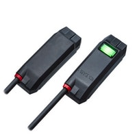
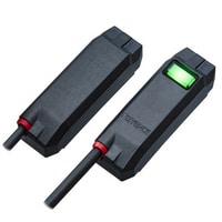
Sensor head
|
Model |
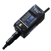
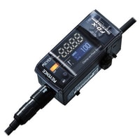
FD-XS1 |
FD-XS8 |
FD-XS20 |
|||
|
Image |
|
|
|
|||
|
Supported pipe materials |
Metal pipes, Plastic pipes (soft/hard) *1 |
|||||
|
Supported fluids |
Liquids (water, oil, adhesive, grease, chemical solutions, etc.) *1 |
|||||
|
Supported fluid temperature |
0 °C (no freezing on the pipe surface) to 100 °C 32 to 212 °F (Pipe surface temperature) |
|||||
|
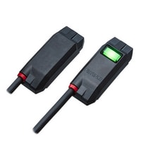
Clamp set model |
Plastic pipe/tube attachment |
FD-XC1R1, FD-XC1R2 |
FD-XC8R1, FD-XC8R2, FD-XC8R3 |
FD-XC20R1, FD-XC20R2, FD-XC20R3, FD-XC20R4 |
||
|
Metal pipe attachment |
FD-XC1M*2 |
FD-XC8M*2 |
FD-XC20M1, FD-XC20M2*2 |
|||
|
Maximum rated flow rate |
0 to 1000 mL/min |
Outer diameter of pipe ø 6 0.24 ", 1/4 " (6.35 mm) : 0 to 3000 mL/min |
Outer diameter of pipe 3/8 " (9.53 mm) , ø 10 0.39 ", ø 10.5 0.41 ": 0 to 15.00 L/min |
|||
|
Zero cut flow rate |
20 mL/min*3 (variable, default) |
40 mL/min*3 (variable, default) |
0.10 L/min (standard), 40 mL/min (high resolution*7)*3 (variable, default) |
|||
|
Display resolution |
Instantaneous flow rate |
0.1/1/10 mL/min (Displayed on controller) |
0.001/0.01/0.1 L/min (standard), 0.1/1/10 mL/min (high resolution*7) (Displayed on controller) |
|||
|
Shot amount |
0.001/0.01/0.1/1 mL (Displayed on controller) |
0.001/0.01/0.1 L (standard), 0.001/0.01/0.1/1 mL (high resolution*7) (Displayed on controller) |
||||
|
Repeatability |
Plastic pipe/tube attachment |
Response time: 50 ms |
F.S. |
± 0.6 %*4*5 |
± 0.1 %*4*5 |
|
|
Instantaneous flow rate |
±6 mL/min*4*5 |
Outer diameter of pipe ø 6 0.24 ", 1/4 " (6.35 mm) : ±3 mL/min |
Outer diameter of pipe 3/8 " (9.53 mm) , ø 10 0.39 ": ±15 mL/min |
|||
|
Response time: 500 ms |
Instantaneous flow rate |
±1.9 mL/min*4 |
Outer diameter of pipe ø 6 0.24 ", 1/4 " (6.35 mm) : ±1.0 mL/min |
Outer diameter of pipe 3/8 " (9.53 mm) , ø 10 0.39 ": ±4.7 mL/min |
||
|
Metal pipe attachment |
Response time: 50 ms |
F.S. |
± 1 %*4*5 |
Outer diameter of pipe ø 6 0.24 ", 1/4 " (6.35 mm) : ±0.3 % |
±0.15 %*4*5 |
|
|
Instantaneous flow rate |
±10 mL/min*4*5 |
Outer diameter of pipe ø 6 0.24 ", 1/4 " (6.35 mm) : ±9 mL/min |
Outer diameter of pipe 3/8 " (9.53 mm) , ø 10 0.39 ", ø 10.5 0.41 ": ±23 mL/min |
|||
|
Response time: 500 ms |
Instantaneous flow rate |
±3.2 mL/min*4 |
Outer diameter of pipe ø 6 0.24 ", 1/4 " (6.35 mm) : ±2.9 mL/min |
Outer diameter of pipe 3/8 " (9.53 mm) , ø 10 0.39 ", ø 10.5 0.41 ": ±7.2 mL/min |
||
|
Hysteresis |
Variable |
|||||
|
Integrated unit display |
0.1/1/10/100/1000/10000 mL (displayed on controller) |
0.01/0.1/1/10/100 L (standard), 0.1/1/10/100/1000/10000 mL (high resolution*7) (displayed on controller) |
||||
|
Display method |
Status indicator |
|||||
|
Environmental resistance |
Enclosure rating |
IP65/IP67 (IEC60529) , IP68G (JIS C0920) *6 |
||||
|
Ambient temperature |
0 to 60 °C (No freezing) 32 to 140 °F |
-10 to 60 °C (No freezing) 14 to 140 °F |
||||
|
Relative humidity |
35 % to 85 %RH (No condensation) |
|||||
|
Vibration resistance |
10 to 55 Hz, double amplitude 1.5 mm 0.06 ", 2 hours each for X,Y,Z direction |
|||||
|
Shock resistance |
50 G 11 ms 3 times each for X,Y,Z direction |
|||||
|
Material |
Sensor head |
Head body: PPS/PPSU, in-cable amplifier: PPS, cable: PVC, controller connector: PPS/PBT/POM |
||||
|
Clamp set |
For plastic pipe |
Body, fixing screw: PPS, detection surface: special rubber, pipe support rubber: FKM, sensor head fixing screw: SUSXM7 |
||||
|
For metal pipe |
Metal: SUS304/SUSXM7, detection surface: special rubber, clamp support rubber: FKM, sensor head fixing screw: SUSXM7 |
|||||
|
Weight |
Approx. 230 g |
Approx. 250 g |
Approx. 260 g |
|||
|
*1 Liquid must allow for the passage of an ultrasonic pulse, as well as not contain large air pockets or excessive bubbles. Readings may become unstable depending on the type of pipe. |
||||||
Controller
|
Model |
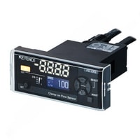
FD-XA1 |
FD-XA2 |
FD-XA5 |
|||
|
Image |
|
|
|
|||
|
Type |
DIN rail type, main unit |
DIN rail type, expansion unit |
Panel type, main unit |
|||
|
Display method |
Output indicator, 4-digit 7 segment display, OLED, Stability level display |
|||||
|
Display refresh frequency |
Instantaneous flow: approx. 5 times/second, Discharge amount/Accumulated flow approx. 30 times/second |
|||||
|
Response time |
50 ms/100 ms/500 ms/1 s/2.5 s/5 s/10 s/30 s/60 s (selectable, default: 500 ms) |
|||||
|
Integration data storage interval |
Written to the memory every 10 seconds |
|||||
|
Memory back up |
EEPROM (data storage period: more than 10 years, number of data rewritable times: 1 million times or more) *1 |
|||||
|
Detection mode |
ch.1 |
Instantaneous flow rate mode/Area mode/Pulse output (+) mode/Integrated flow mode/Shot mode (selectable) |
||||
|
ch.2 |
Instantaneous flow rate mode/Area mode/Pulse output (-) mode/Shot mode/Error output mode/Bubble alert mode/Error + bubble alert mode (selectable) |
|||||
|
Input/output |
Output |
NPN/PNP setting switch |
||||
|
Analog output |
4-20 mA/0-20 mA (selectable) load resistance: 500 ohms or lower |
- |
4-20 mA/0-20 mA (selectable) load resistance: 500 ohms or lower |
|||
|
External input |
Flow rate zero input/shot sampling input/integrated flow reset input/zero shift input (selectable) |
|||||
|
Network support |
IO-Link*3 |
Supports NU series |
IO-Link*3 |
|||
|
Unit expansion |
Up to 7*4 per main unit |
- |
||||
|
Protection circuit |
Power supply reverse connection protection, power surge protection, output short circuit protection, output surge protection |
|||||
|
Power supply |
Power voltage |
20 to 30 VDC including 10 % ripple (P-P) , Class 2 |
||||
|
Power consumption |
195 mA or lower (including the sensor head, excluding the load current) |
185 mA or lower (including the sensor head, excluding the load current) |
195 mA or lower (including the sensor head, excluding the load current) |
|||
|
Environmental resistance |
Ambient temperature |
-10 to +50 °C (No freezing) 14 to 122 °F |
||||
|
Relative humidity |
35 % to 85 %RH (No condensation) |
|||||
|
Vibration resistance |
10 - 55 Hz, double amplitude 1.5 mm 0.06 ", 2 hours each for X,Y,Z direction |
|||||
|
Shock resistance |
100 m/s2 (approx. 10 G) 16 ms pulse, 1000 times each for X,Y,Z direction |
|||||
|
Material |
Main body case/front sheet: PC, Key top: POM, Cable: PVC |
|||||
|
Weight |
Approx. 210 g |
Approx. 180 g |
Approx. 210 g |
|||
|
*1 Internal data from full time recording can be read via USB (Ver.2.0) communication. |
||||||