Data Acquisition (DAQ)
3 Ways to Measure Electrical Current with Sensors
-
Tags:
- Current
Measuring the flow of electrical current is one of the most important and near-universal measurements in modern industry. Nearly every quantifiable measurement can be represented via the flow of electrical current. However, not every measurement method applies to specific measurements and applications.
Let’s discuss how you can measure current with sensors and other measuring devices like data loggers or data acquisition systems and provide a detailed explanation of current measurement fundamentals.
Understanding Current Measurement Fundamentals
Before we can explain the current measurement fundamentals, we have to go through the fundamentals of electrical current.
Electrical current is defined as a flow of electrical charge through a conductive material driven by a force or a potential difference (voltage) through a closed circuit. The standard unit of electrical current is ampere or amp (A) and can be either direct (DC), meaning that it flows in a single direction, or alternating (AC), meaning it changes direction periodically.
Conductive materials, like solid metals, usually have a large population of mobile or free electrons. When a metal wire is connected to the two terminals of a DC voltage source—such as a battery—the source places an electric field across the conductor. The moment the circuit closes, the free electrons within the conductor are driven by the potential difference.
This means that if we’re using a battery as a power source, the electrons will flow from the negative battery terminal to the positive terminal, driven by the potential difference between the terminals (voltage).
When measuring electrical current, the flow of electrical charge is measured using a current-measuring device called an ammeter (which measures amperes/amps) or a multimeter—a measuring instrument that can measure multiple electrical properties, including voltage and resistance.
Before you ask yourself how to measure current with sensors, it’s essential to note that there are several different ways. The most common methods are direct measurements and indirect measurements. The former requires that you connect the multimeter in series with the circuit, thus allowing electrical charges to actually flow through the multimeter (or an ammeter).
The latter is far more applicable because it doesn’t require you to break or interrupt the circuit to measure the flow of current. Instead, the measurement might imply measuring the strength of the electromagnetic field around the conductor generated by current flow. This doesn’t require physical contact with the conductor, nor does it interrupt the circuit.
Another method is to incorporate a low-value shunt resistor into the circuit and measure the voltage drop across it, deriving the current value by using Ohm’s law. And the third most commonly used method is a Current Transformer, which reduces the current to values that are safer to measure.
We’re here to provide you with more details.
Reach out today!

How to Measure Current Using Current Sensors
Large industrial settings usually rely on automation systems, data acquisition systems, portable data loggers, and other measuring devices to measure the flow of current. In most cases, large companies typically rely on all of the above.
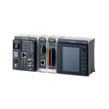
For example, KEYENCE’s NR-X Series multi-input data logger, in combination with NR-HV04/NR-FV04, NR-HA08, NR-HA08P, or NR-TH08 measurement units, can easily measure current flow. However, the exact measurement method mostly depends on the type of measurement unit and the need for a particular application.
Method 1: Current Probes
Measuring current using current probes is a great way to measure the flow of electrical charge without interrupting the circuit. The probe usually contains a direct/alternating current sensor—typically a Hall-effect sensor—and measures the current flowing through the conductor by passing the conductor through the ring structure.
The ring structure contains a hall-effect sensor that detects the strength of the magnetic field, which is proportional to the current flowing through the conductor. It’s an effective way of measuring both DC and AC currents. However, certain precautions are associated with connecting a current probe.
For example, only one wire should go through the current probe. Passing two or more wires could cause the magnetic fields to interfere with one another and offset the measurement by quite a substantial amount. Also, the direction of the probe should match the direction of the current (in the case of DC measurements); otherwise, the sign of the current value will be negative.
Method 2: Shunt Resistors
We have already established that measuring current in a circuit implies interrupting the circuit, which also means interrupting circuit operation. However, voltage is far easier to measure than current because the measuring instruments are connected in parallel, which doesn’t imply breaking up the circuit.
Ohm’s law states that the electric current through a conductor between two points is directly proportional to the voltage across said points, provided that all other physical conditions remain constant—including electrical resistance.
By introducing a known, low-value resistance into the circuit (in series) and measuring the voltage drop across it, the current can be easily calculated indirectly using Ohm’s law, which states that the current equals voltage divided by resistance.
This measurement approach is commonly used with a shunt resistor—a very precise low-value resistor—in high-current applications. The low resistance ensures that the voltage drop across the resistor is minimal, thus severely limiting the resistor’s impact on the circuit’s function.
By measuring the small voltage drop across the shunt resistor and knowing the shunt’s exact resistance value, technicians can accurately measure the value of the current flowing through the circuit.
However, these measurements have some limitations. Using a shunt resistor to measure current requires that you implement an appropriate resistor. Inadequate resistors will certainly produce a measurement error.
To do this, consider the minimum voltage at which the load can work and divide that value by the load’s current consumption. The resulting value, and/or lower, is your shunt resistance. After implementing the resistor into the circuit, you can then derive the current value based on the measured voltage.
KEYENCE’s NR-X Series multi-input DAQ can measure current directly because of a built-in circuit, taking the worry out of choosing the correct resistance value., Otherwise, a resistor in combination with NR-HV04, NR-FV04, and NR-TH08 measurement units, can derive a current value by measuring the voltage drop across a known resistance alue. This is useful when measuring other signal types with the same input module.
Method 3: Current Transformers (CTs)
Current transformers are exceptionally useful in measuring current in high-current AC applications. Transformers are rather simple machines with exceptionally high efficiency of up to 99%. The conductor of interest passes through the CT and acts as the primary winding that generates a magnetic field in the CT’s core.
This magnetic field then induces a current in the secondary winding, which usually has multiple wire turns around the CT’s core. The induced current is proportionally lower than the primary current, based on the turns ratio of CT—the number of primary turns against the number of secondary turns of the wire.
The circuit has to be closed for the current to flow, so a burden resistor is added to the circuit to act as a load. By measuring the voltage across the voltage across the resistor and using Ohm’s law, we can derive the current measurement within the circuit of the secondary winding and multiply it with the turns ratio to get the current value in the primary winding.
Summary
In summary, there are several different ways to approach the question of how to measure current, and most industrial settings typically rely on DAQ systems and other current and voltage measurement devices. If you’re interested in data acquisition solutions and industrial automation aspects of current measurement, KEYENCE’s NR-X Series has you covered.
Contact KEYENCE for more information regarding potential integrations with your current production setup.
Contact us to learn more about how our advanced technology can help take your business to the next level.
Contact Us
Related Downloads

Browse tips on how to select the best DAQ for specific conditions and applications for current measurement with a focus on the measurable current types, number of channels, sampling rate, and simultaneous measurement of other input signals.


