3D Scanner
How to Accurately Measure Product Thickness Non-Destructively
-
Tags:
- Plastics
Key Takeaways
- VL Series performs non‑contact 360° scans to measure full part thickness.
- Create virtual cross‑sections to measure complex or enclosed wall thickness.
- Color‑map deviation vs. CAD highlights min/max thickness and reduction zones.
- Single‑shot scans (~8 s) remove operator variability and enable fast OK/NG.
- Non‑destructive method avoids cutting and deformation for accurate thickness data.
Measuring thickness during product inspection can be a challenge. While it is easy to measure simple, uniformly thick products like films, accurately measuring the thickness of complex shapes, such as stamped or molded plastic parts, non-destructively is difficult.
Traditionally, thickness is measured using tools like calipers, caliper gauges, or micrometers. However, for complex shapes, these tools may not be able to physically reach the measurement area. In such cases, the only option is destructive testing, which involves cutting the sample for measurement. But depending on the sample, cutting can cause deformation, affecting the measurement values.
KEYENCE's VL Series 3D Scanner CMM can solve these problems. Here, we will clearly explain the shapes and materials that are difficult to measure, the challenges of conventional measurement methods, and how KEYENCE's VL Series provides a solution.
Thickness Measurement Challenges in Manufacturing
Manufacturing products and parts from materials like metal and plastic requires selecting appropriate processing methods based on the desired shape, application, and material properties. While these diverse manufacturing techniques enable the creation of complex geometries and functional designs, they also introduce unique measurement challenges.
Certain shapes, materials, and processing methods create parts whose thickness is particularly difficult to measure accurately. Let's explore these challenging cases and understand why conventional measurement approaches often fall short.
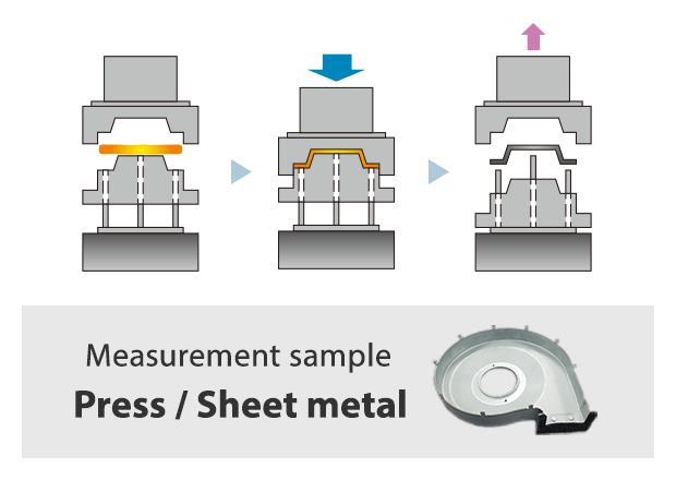
Stamped Parts
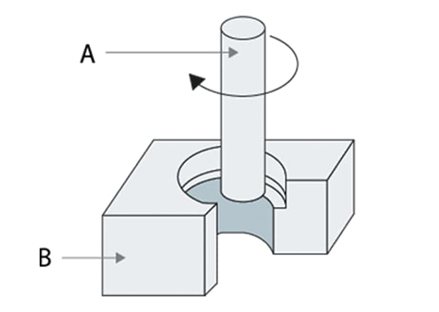
Stamping is a forming process that shapes materials like metal by pressing them against a die under high pressure. This plastic deformation technique encompasses three main process types: cutting (shearing), bending, and drawing. The speed and efficiency of stamping make it ideal for high-volume production at low cost.
However, the forces involved in stamping create measurement considerations. During processing, the material experiences significant stress and friction, which can cause thickness variations throughout the part. These variations make post-processing thickness measurement important to ensure parts meet quality specifications.
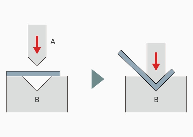
A: Pressing B: V-groove
Bent Parts
Bending is a forming process that shapes materials like metal or plastic by applying force or heat. This can be accomplished mechanically by applying pressure to fold the material, or thermally by heating the material to make it pliable for deformation.
When metal is bent using a die—a process classified as a type of stamping and commonly referred to as "press bending"—significant pressure is applied to deform the material. This pressure not only creates the desired bend but also causes changes in the material's thickness, particularly at the bend radius where the material is compressed or stretched.
Machined Parts
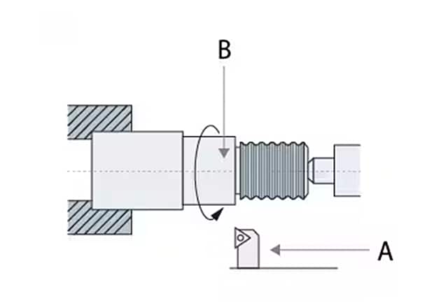
Machining is a process that uses cutting tools to shape materials like metal into desired forms. Common machining methods include milling, which uses rotating cutters on a milling machine, and turning, which shapes parts on a lathe.
During machining, the cutting tool applies significant force to the part, introducing multiple factors that affect dimensional accuracy. The contact pressure and vibration from the cutting process can cause mechanical deformation, while the heat generated during cutting leads to thermal expansion. These combined effects alter the part's dimensions, making post-processing measurement essential to verify that parts meet specifications.
A: Cutting tool B: Workpiece
Die-Cast Parts
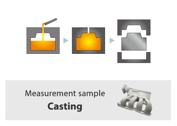
Die casting is a casting technique in which molten non-ferrous metal is poured into a mold under pressure to form parts. This pressurized approach sets die casting apart from other casting methods, delivering superior dimensional accuracy and enabling the creation of complex three-dimensional shapes that would be difficult or impossible to achieve through sheet metal or stamping processes.
However, the intricate geometries and free-form surfaces that make die casting so versatile also present measurement challenges. The complex contours of die-cast products often make accurate thickness measurement difficult with conventional tools.
Molded Plastic Parts
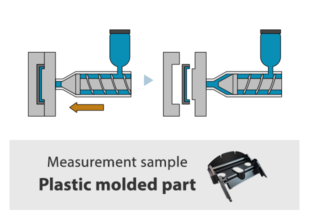
Plastic molding is a manufacturing method that creates parts and products by pouring molten resin (plastic) into a mold. The most common approach is injection molding, in which heated resin is injected into a mold cavity, then pressurized and cooled to form the final part.
This process excels at rapidly producing thin-walled components with complex geometries. However, injection-molded parts present unique measurement challenges. Their intricate shapes often have areas that are difficult or impossible to reach with traditional calipers. Additionally, depending on the material properties, contact-based measuring instruments can cause deformation, making accurate thickness measurements particularly difficult to obtain.
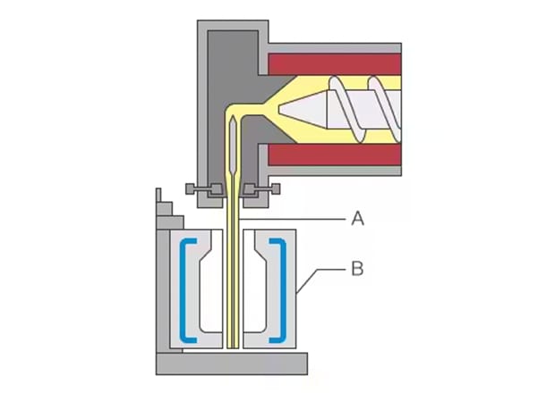
A: Parison (Hot parison) B: Mold
Preform and Blow Molded Parts
PET bottles and similar containers are prime examples of molded plastic parts with hard-to-measure thickness. Their enclosed design prevents calipers from accessing interior surfaces, making conventional measurement methods impractical.
These bottles are typically manufactured through a two-step process: preform molding followed by blow molding.
Thickness Measurement Methods: Capabilities and Limitations
Measuring sheet and wall thickness in manufactured parts requires different approaches depending on the geometry, material, and accessibility of the measurement area. Each method offers distinct advantages while facing specific challenges that affect accuracy and applicability.
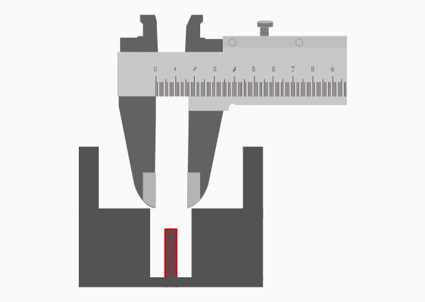
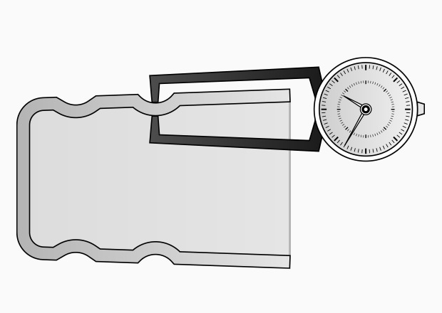
Calipers and Caliper Gauges
Calipers and caliper gauges are among the most widely used tools for measuring product thickness. Calipers measure length, outer diameter, inner diameter, and thickness by clamping the target between their jaws. Caliper gauges (also called thickness gauges) are scissor-like instruments that measure dimensions by clamping the workpiece between probe tips.
Both tools are straightforward to use, but they have several limitations for thickness measurement:
Limited accessibility: The jaws or probes cannot always reach the measurement location, particularly with complex geometries, internal features, or recessed areas.
Single-point measurement: Since these instruments capture thickness at only one location, they cannot provide a complete picture of the part's dimensional characteristics, such as identifying the maximum or minimum thickness across a surface.
Contact-induced deformation: As contact-based measurement tools, both calipers and caliper gauges apply mechanical pressure to the measurement area. This pressure can deform soft materials or thin-walled parts, compromising measurement accuracy.
Infrared/Radiation Thickness Gauges
For applications where contact-based measurement is impractical, infrared and radiation thickness gauges offer non-contact alternatives. Infrared gauges measure thickness by exploiting the transmission properties of infrared light through certain materials. Radiation gauges, on the other hand, determine thickness by measuring how much radiation is absorbed as it passes through the sample.
The non-contact nature of these methods eliminates the risk of deforming delicate or soft materials. However, both technologies require large-scale equipment, which can be costly and space-intensive. Additionally, like single-point contact gauges, these instruments measure thickness at discrete locations rather than capturing comprehensive surface profiles, limiting their ability to characterize overall part geometry or identify localized variations across the part.
Destructive Testing
When measurement points are inaccessible to contact-based tools and non-contact methods are unavailable, the traditional approach was destructive testing—physically cutting the sample to measure its cross-section. While this method can reveal internal thickness dimensions, it presents several significant drawbacks.
Process-induced errors: The cutting process itself can alter the dimensions being measured, particularly with molded plastic parts. Heat, mechanical stress, and material deformation during sectioning can compromise measurement accuracy.
Sample destruction: Since the part must be destroyed to obtain measurements, this approach is inherently wasteful. The destructive nature also makes 100% inspection impossible so that only sample-based quality control can be performed, leaving the possibility that defective parts remain undetected.
Limited data capture: Even after cutting, thickness is typically measured using calipers or caliper gauges on the exposed cross-section. This provides only point-based measurements at the cut location, offering no insight into thickness variations across the entire part or surface profile characteristics.
These limitations make destructive testing a last resort when other measurement methods are not feasible.
The Coverage Gap in Traditional Measurement Methods
While multiple methods exist for measuring thickness, they share a fundamental limitation: most conventional techniques capture data at discrete points rather than across entire surfaces. This point-based approach makes it difficult to characterize complete part geometry or identify critical dimensional features such as maximum and minimum thickness locations.
To compensate for this limitation, operators must take measurements at numerous points across the part which is both time-consuming and labor-intensive. Even with multiple measurements, gaps between sampling points mean that localized variations or defects may go undetected. This creates a trade-off between measurement thoroughness and practical efficiency, often leaving manufacturers uncertain whether their quality assessment truly captures the full dimensional profile of their parts.
How to Accurately Measure Product Thickness Non-Destructively
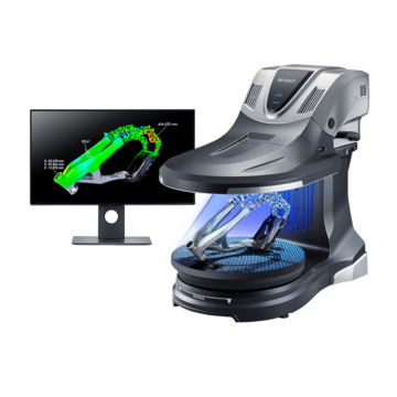
To address the limitations of conventional thickness measurement methods, KEYENCE's VL Series 3D Scanner CMM offers a comprehensive solution that combines non-contact measurement with full-surface data capture.
Complete non-contact measurement: The VL Series uses 3D scanning technology to measure thickness without physical contact, eliminating deformation risks associated with calipers, cutting, or other mechanical probes. This enables accurate measurement of soft materials, thin-walled parts, and delicate components.
Full-surface characterization: Unlike point-based methods, the VL Series captures the complete 3D geometry of both front and back surfaces, regardless of part complexity. This provides a comprehensive thickness profile across the entire part, revealing maximum and minimum values as well as localized variations that discrete measurements might miss.
Speed and consistency: The system can scan an entire part in as little as 8 seconds, dramatically reducing measurement time compared to manual multi-point approaches. The automated scanning process also eliminates operator-to-operator variability, ensuring repeatable and reliable results.
Let's explore the specific advantages of using the VL Series for product thickness measurement.
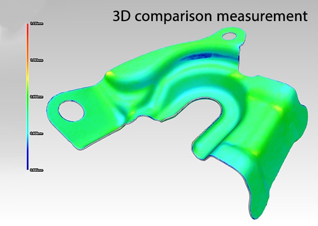
Benefit 1: Visual thickness analysis with color mapping
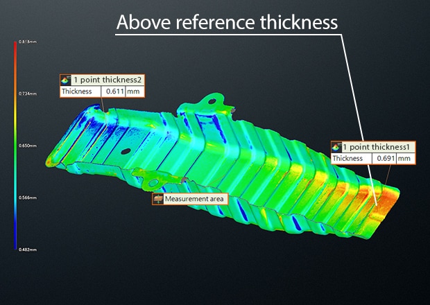
The VL Series transforms thickness measurement from discrete numerical values into comprehensive visual analysis through color map visualization. This feature displays thickness variations across the part's entire surface using an intuitive color gradient, making it easy to identify areas that deviate from design specifications.
After capturing the complete 3D geometry through 360° scanning, the system compares measured thickness against design values at every point on the surface. Thickness variations are then displayed as a color map, where different colors represent how much each area exceeds or falls short of target dimensions. This allows you to instantly identify potential defect areas, thin spots, or excessive material buildup that might indicate molding issues, uneven material distribution, or process problems.
Unlike point-based methods that require mentally connecting discrete measurements to understand overall part quality, the color map provides immediate visual feedback across the entire surface. Areas requiring attention stand out immediately, enabling faster decision-making and more efficient quality control. This comprehensive surface analysis—impossible with traditional measurement approaches—allows you to evaluate thickness easily, accurately, and at a glance.
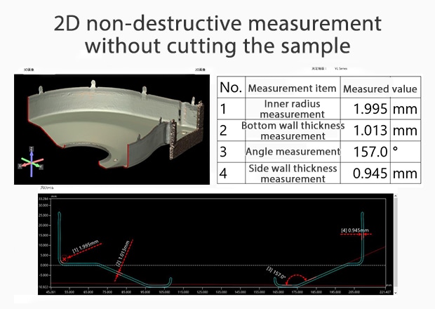
Benefit 2: Easy, non-destructive measurement of complex shapes
Conventional methods struggled with complex geometries, often requiring destructive cutting to access internal features or hard-to-reach areas. The VL Series eliminates this limitation by capturing complete 3D geometry non-destructively, enabling thickness measurement of even the most intricate shapes without damaging the part.
After scanning, you can create virtual cross-sections at any location or angle to analyze internal wall thickness, measure depth profiles, or inspect features that would be inaccessible with contact-based tools. This virtual sectioning provides the same insights as physical cutting, but without destroying the sample.
The system also automatically detects part size and adjusts scan parameters, handling components of varying scales without manual configuration. This eliminates tedious fixture setup and complex programming, allowing measurement of complex geometries with minimal preparation.
The automated scanning process delivers repeatable accuracy regardless of user experience. Unlike manual methods where measurement quality depends on operator skill and technique, the VL Series ensures every scan captures the same comprehensive data, eliminating variation and reducing training requirements.
By combining non-contact 3D scanning with intelligent automation, the VL Series makes thickness measurement of complex shapes straightforward and accessible—transforming what was once a challenging, destructive process into a simple, repeatable operation.
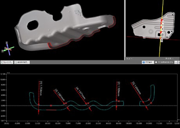
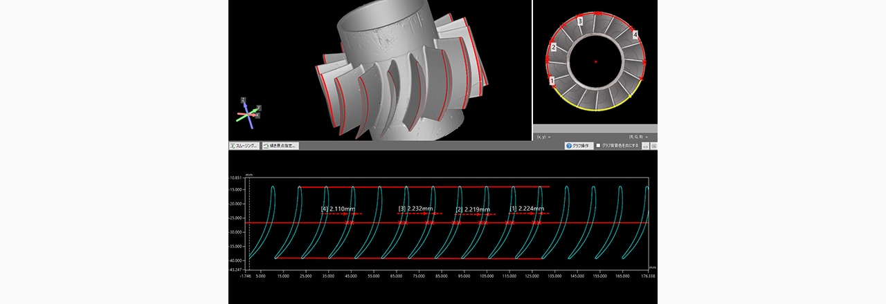
Benefit 3: Measuring free-form surfaces and inaccessible features
Free-form surfaces with complex curves and contours present significant challenges for conventional measurement tools. Calipers cannot conform to curved surfaces to measure thickness accurately, while traditional touch-probe CMMs fail when measuring overlapping features, internal cavities, or enclosed geometries where the stylus cannot physically reach.
The VL Series overcomes these limitations through non-contact 3D scanning. By capturing the complete external geometry, the system enables virtual cross-sectioning at any location and angle, including areas that would be physically inaccessible to a probe. This allows you to measure wall thickness in curved sections, analyze overlapping features, and inspect internal structures without requiring physical access.
Beyond direct thickness measurement, the VL Series can import 3D CAD data for comprehensive comparison against design intent. The system overlays measured geometry with the CAD model to calculate deviations across the entire surface, instantly revealing where the part differs from specifications. This comparison identifies not only thickness variations but also dimensional shifts, warpage, or form errors. Users can even compare 3D scans against each other to monitor any changes in manufacturing process.
The results can be displayed as a color map showing deviation magnitude across the part, making it easy to assess conformance to design requirements. This visual analysis quickly highlights areas exceeding tolerance limits, enabling rapid quality decisions for even the most complex free-form geometries.
Achieve Non-Destructive and Accurate Thickness Measurement
KEYENCE's VL Series 3D Scanner CMM transforms thickness measurement from a challenging, time-consuming process into a fast, reliable, and non-destructive operation—regardless of part complexity or material.
Key Capabilities
Create virtual cross-sections at any location to measure thickness in free-form surfaces, curved features, and inaccessible areas that defeated conventional tools.
Compare measured thickness against design specifications and display deviations as intuitive color maps for instant quality assessment.
Measure delicate materials, thin-walled parts, and soft plastics without risk of deformation or damage.
Operational Advantages
Complete full-surface scans in as little as 8 seconds, dramatically reducing measurement time compared to manual multi-point approaches.
Non-contact automated scanning eliminates operator-to-operator variation, ensuring repeatable results regardless of user experience.
Quantitative comparison tools and visual deviation mapping make pass/fail decisions straightforward, streamlining inspection workflows.
The VL Series delivers what conventional methods cannot: comprehensive, accurate, non-destructive thickness measurement for any shape or material. Transform your quality control process and eliminate the compromises inherent in traditional measurement approaches.