3D Scanner
Precision Measurement to Prevent Defects in Injection-Molded Parts
-
Tags:
- Plastics
Key Takeaways
- Improve yield through full 3D scanning and comparison against CAD models.
- The VL Series captures entire parts in one scan to rapidly identify warpage, sink marks, and shrinkage.
- Overlay scans from different molding conditions to pinpoint subtle shape variations.
- Convert scan data to CAD for simulation analysis and mold design improvements.
- Automated 3D inspection surpasses traditional CMM and optical comparator methods with non-contact, comprehensive analysis.
Molding defects remain one of the most significant challenges facing the plastic molding industry. Material differences and subtle variations in molding conditions can trigger these defects, ultimately reducing production yield and compromising quality.
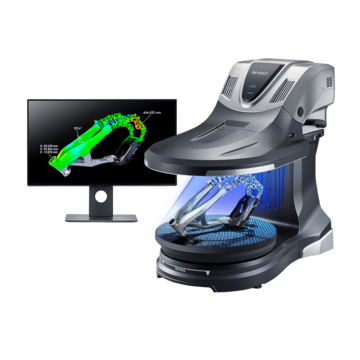
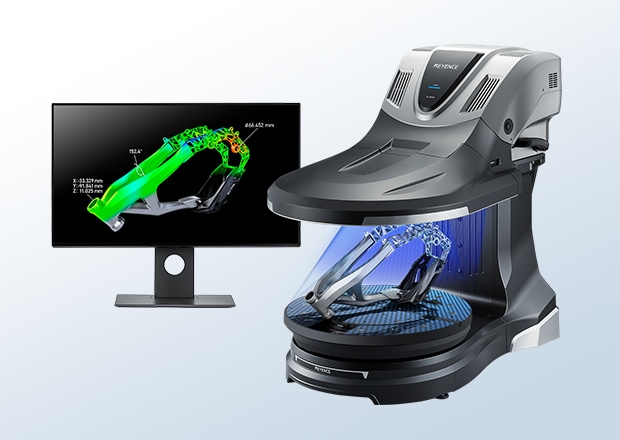
In recent years, 3D scanning technology has emerged as a promising solution. KEYENCE's VL Series 3D Scanner CMM precisely measures the shape of molded parts and captures digital data, enabling manufacturers to directly tackle molding defect issues while significantly improving both process efficiency and overall quality.
By visualizing molding defect problems, the VL Series helps manufacturers identify root causes and implement effective solutions, leading to improved yield rates.
Discover more technical information on molding defects and learn how the VL Series can transform your production process.
What Are Molding Defects?
Molding defects refer to problems that occur during the plastic molding process, encompassing any phenomenon that compromises product quality. These defects manifest in various ways, including products that don't match design specifications and dimensional inaccuracies to surface imperfections.
Beyond degrading product performance, molding defects have far-reaching consequences on production efficiency and costs, making their elimination one of the manufacturing industry's most critical challenges.
Types of Molding Defects and Countermeasures
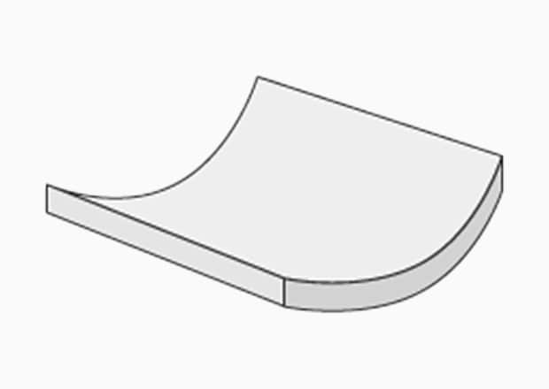
Warpage
Warpage occurs when a molded part shrinks unevenly during cooling, causing shape distortion. This defect typically results from non-uniform cooling rates or variations in the material's flow direction.
To prevent warpage, manufacturers should review their cooling methods and optimize molding conditions, as proper temperature control and processing parameters are essential to maintaining dimensional accuracy.
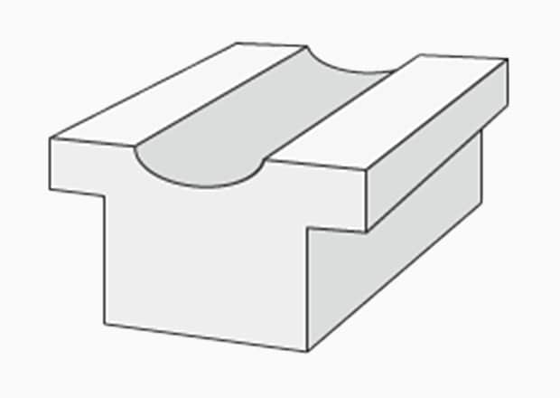
Sink Marks
Sink marks appear as surface depressions on molded parts, typically caused by insufficient resin filling or non-uniform cooling rates. To prevent sink marks, manufacturers can adjust injection pressure or modify their cooling methods, as maintaining adequate pressure throughout the injection process and ensuring consistent cooling are critical to achieving smooth, defect-free surfaces.
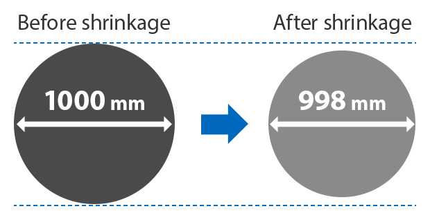
Shrinkage
Shrinkage occurs when molded parts contract during cooling, resulting in dimensions smaller than the original design specifications. This defect stems from the resin's inherent shrinkage rate and mold design characteristics. To compensate for shrinkage, manufacturers should carefully evaluate material selection and optimize mold design to account for anticipated dimensional changes.
Current Measurement Challenges
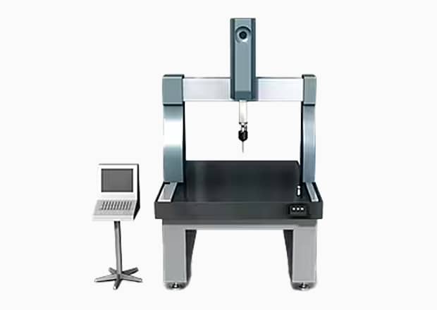
Coordinate Measuring Machines (CMMs)
Coordinate Measuring Machines (CMMs) are precision devices that measure product shape and dimensions through contact with a stylus. While highly accurate, traditional CMMs face several operational challenges that can impact production efficiency.
Measurement time presents a significant concern, particularly for products with complex shapes. Since analyzing molding defects requires acquiring numerous data points to capture the overall geometry, extended measurement cycles become inevitable. These lengthy processes can create bottlenecks in production workflows.
Beyond time constraints, CMMs demand specialized knowledge and technical expertise to operate effectively. This requirement translates to substantial investments in training and education, adding both time and cost to implementation.
× The stylus cannot reach intricate shapes
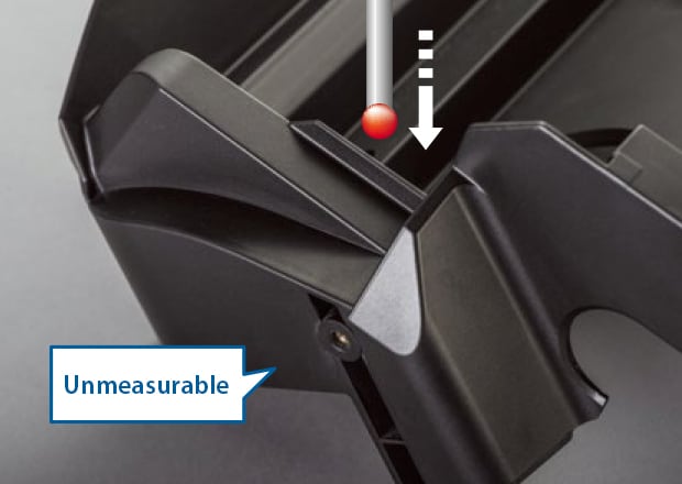
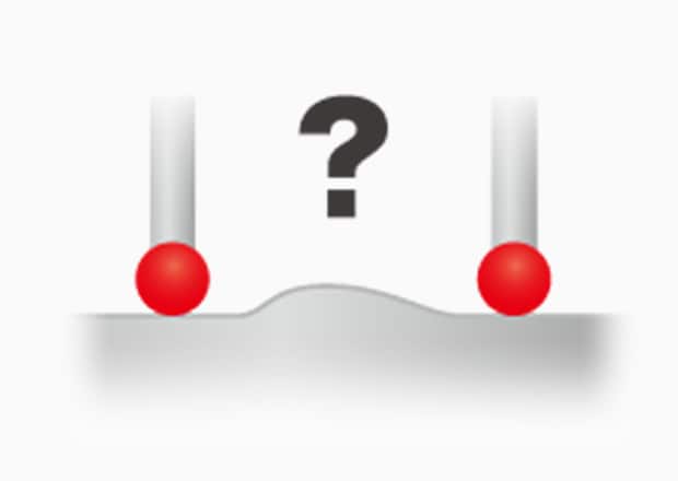
× Limited measurement points make it difficult to understand the overall shape
Optical Comparators
Optical comparators measure product shape and dimensions by projecting a magnified shadow or profile onto a measurement screen. While this approach provides non-contact inspection, the fundamental 2D nature of the technology creates inherent limitations for modern manufacturing needs.
The core challenge lies in the projection principle itself: optical comparators can only capture features visible in a single plane at any given time. This makes them effective for simple profiles and cross-sections, but inadequate for evaluating complex three-dimensional geometries common in plastic molded parts. Features like warpage, surface curvature variations, and multi-planar defects simply cannot be fully characterized from a 2D silhouette.
Furthermore, attempting to work around these limitations proves labor-intensive. Operators must repeatedly reposition and reorient parts to capture different viewing angles, transforming what should be a quick inspection into a time-consuming process. Each repositioning also introduces potential alignment errors, compounding measurement uncertainty. For comprehensive molding defect analysis, which requires understanding the complete 3D form, optical comparators demand excessive manual intervention while still providing incomplete data.
× Limited measurement range
× Difficult to perform 3D evaluation

Application Examples with the VL Series 3D Scanner CMM
Molded Part Inspection
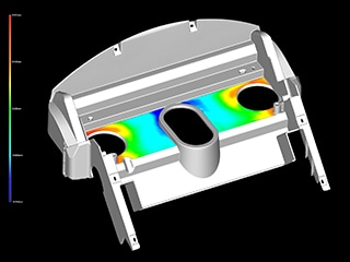
The VL Series captures data from the entire molded part. This comprehensive approach generates detailed color maps that visualize warpage, sink marks, and surface changes across the complete geometry.
Unlike traditional point-based measurements that provide only isolated data points, full-surface scanning reveals overall shape trends and patterns critical for effective defect analysis. This holistic view enables engineers to identify root causes more quickly and implement targeted corrections with greater confidence.
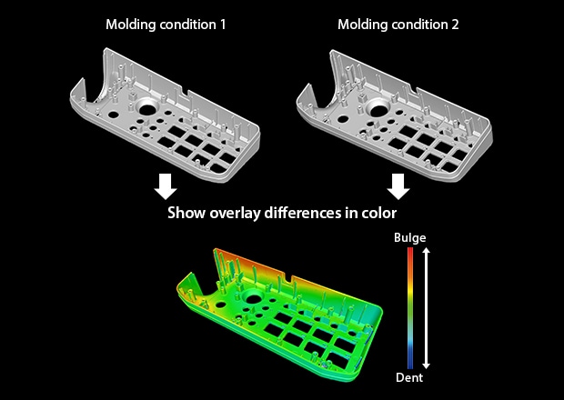
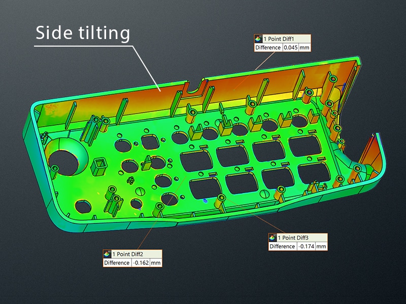
The VL Series overlays scan data from two samples, revealing differences through intuitive color mapping. When comparing parts molded under varying conditions, this visualization exposes subtle deviations such as wall tilt and thickness variations that would otherwise go undetected.
Beyond process optimization, this comparative capability proves invaluable for quality troubleshooting. By overlaying defective parts against known good samples, engineers can instantly pinpoint failure locations and implement corrective actions before yield losses escalate.
Integration with 3D CAD Data
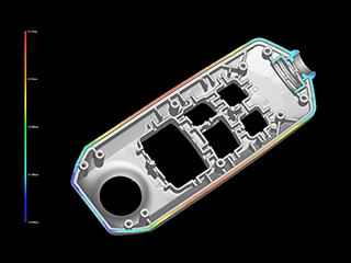
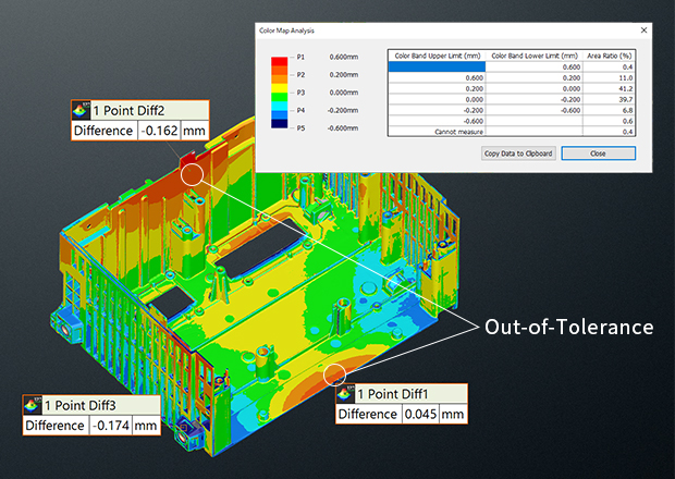
The VL Series compares scanned part data directly against 3D CAD models, visualizing deviations using a heigh-color map. This immediate visual feedback highlights exactly where the molded part diverges from design specifications.
Going beyond simple visualization, the system quantifies these deviations by calculating the area percentage within each tolerance band. Engineers can instantly assess not only where discrepancies occur, but also their severity and scope—enabling faster, more informed decisions about process adjustments and quality control.
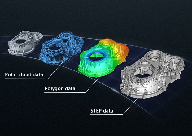
The VL Series transforms physical molded parts into accurate 3D CAD data in a streamlined workflow. This digitized geometry serves as the foundation for Computer-Aided Engineering (CAE) analysis, enabling engineers to simulate critical factors such as resin flow behavior and identify potential design weaknesses.
Armed with these insights, engineers can refine mold designs before production begins. By addressing issues at the design stage, rather than discovering them through trial and error, manufacturers can minimize molding defects from the outset and significantly improve first pass yield.
Summary
Proactive Prevention: Optimize Before Production
Design files inevitably differ from actual molded parts due to material behavior and process variables. The VL Series closes this gap by converting physical samples into accurate CAD data, enabling engineers to perform CAE analysis on real-world geometry rather than theoretical designs. This approach allows mold design refinement based on actual performance, reducing molding defects before full production begins.
Reactive Response: Rapid Root Cause Analysis
When molding defects do occur, time is critical. Prolonged troubleshooting directly translates to mounting yield losses. The VL Series accelerates defect identification by comparing failed parts against CAD specifications or known good samples. This immediate visual analysis pinpoints problem areas quickly, enabling engineers to implement corrective actions and prevent defect recurrence.