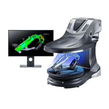
3D Scanner
Accurately Measure Plastic Molded Parts
-
Tags:
- Plastics , Plastic molding
Key Takeaways
- Plastic molded parts can be difficult to inspect because of soft materials, complex shapes, and tight tolerances.
- 3D scanners improve plastic part measurement by capturing full geometry without touching or deforming the surface.
- Non-contact scanning supports inspection, quality control, and reverse engineering for molded plastic components.
- Compared with traditional tools, 3D scanning can improve repeatability and reduce measurement challenges on delicate parts.
Learn how 3D scanning technology solves common measurement problems for plastic molded parts. We'll cover the main types of molding plastic, defects that cause fitting failures, and why non-contact measurement delivers better results than traditional methods like coordinate measuring machines or calipers.
Plastic molding allows large quantities of products to be produced for lower cost and with higher precision when compared with metal or ceramic products. As it is superior for inexpensive commercial production compared with machining methods such as cutting and pressing, parts that were made of aluminum for prototyping are often changed to plastic for commercial production.
However, injection and blow defects can occur easily as a result of abnormal viscosity, temperature, or pressure during molding, and shape defects can occur as a result of mold wear. Due to the characteristics of the plastic, there is also the possibility of deformation due to residual stress or thermal stress occurring even after molding. These defects are fatal problems for assembly/fitting parts that require particular precision, and are major problems that lead directly to product malfunctions or assembly/fitting failures.
Here we will introduce the major plastic molding methods and defects, as well as methods for prototype measurement during development and design, and measurement methods for preventing the outflow of defective products in commercial production. We will also introduce problems with conventional measurement methods and solutions for resolving them.
Plastic Molding
Plastic molding is a method of forming a product that heats and melts plastic in order to inject it into a mold. After forming the specified shape, the part is cooled inside the mold before being removed. Forming uses a method that is suitable for the application and shape, making use of the characteristics of various plastic molding materials.
One type of molding material is thermoplastic resins that become plastic as a result of heating. These are provided in the form of granular pellets. Another type is thermosetting resins that solidify as a result of heating. These are provided in powder form. Pellets and powders that also contain additives for improving function or coloring materials are used in some cases.
For stable plastic molding, it is important to control molding conditions such as mold temperature, plastic material quantity, and injection speed. In each process, it is also necessary to pay attention to preventing the entry of dust or dirt, as well as preventing particles of foreign matter from adhering due to static electricity.
Types of Plastic Molding
Plastic molding methods are mainly classified as injection molding, blow molding, extrusion molding, and calendar molding. Among these, injection molding and blow molding are the most typical molding methods that are widely used. This section explains these two molding methods.
Injection Molding
With injection molding, heated and melted plastic is shaped by injecting it into a mold. As the plastic material is injected at high pressure, thin-walled products and products with complex shapes can be formed at high speed, making this method suitable for commercial production. It is mainly used for molding of thermoplastic resins, but infrequently it is also used for molding of thermosetting resins.
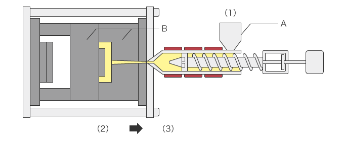
A : Hopper B : Mold
Basic Mechanism of Plastic Molding (Example of Injection Molding)
The basic principle of injection molding is shown below.
(1) The plastic material is supplied from a hopper, and is heated and melted to plasticize it.
(2) It is then formed into a certain shape using a mold or similar tool.
(3) It then cools and hardens in the shape of the mold.
In the next step, the molded part is removed from the machine and passes through various processes and inspections to become the plastic product. Major products that are produced by injection molding include the following.
- Smartphone covers
- Electric appliance housings, plastic model kits
- Toilet seats
- Automobile bumpers and instrument panels
Injection molding can be described as the most common method of plastic molding because it is used in molding and commercial production of such a wide range of plastic products of all sizes. Injection molding is further classified into the following methods according to the product which is manufactured.
|
Insert molding
|
With this molding method (also called composite molding), an insert such as a metal screw or terminal is placed inside the mold in advance, and then plastic is injected around the insert to mold it together with the insert.
|
|---|---|
|
Multi color molding / Multi material molding
|
With these methods, plastics of different colors or materials are combined to mold a single product.
|
|
Film insert molding and film-in-mold molding
|
Film insert molding and film-in-mold molding are employed for surface decoration such as a logo or characters on plastic parts, membrane switches of electrical appliances, and automobile interiors (shift panels and other plastic parts). They are also referred to as “decorative molding.”
With film insert molding, a film printed with a pattern or a gloss or matte film (decorative film) is set inside the mold in advance, and the film and plastic are bonded together in the mold by heat and pressure during the injection molding process. With film-in-mold molding, a decorative film is set inside the mold in advance, and then the decoration of film is transferred onto the plastic during the injection molding process. |
Blow Molding (Hollow Molding)
With blow molding, heated and melted plastic is extruded in a tube shape and placed into the mold, then air is blown into the inside to inflate and shape the plastic. This method is suitable for producing plastic molded products that have hollow interiors, and it is also referred to as “hollow molding” because of the production method. Major products produced by blow molding include the following.
- Plastic drink bottles
- Containers for products such as liquid cosmetics and liquid detergents
- Tubes
- Tube joints
When the product will be filled with liquid, it may be necessary to select the type of plastic according to the liquid characteristics. For example, when it is necessary to prevent oxidation caused by permeation of oxygen, a plastic which has a gas barrier property is used. When chemical resistance is required, multiple molding materials, including plastics that do not deteriorate when exposed to chemicals, are molded in layer form.
There are various blow molding methods used according to the product being produced. This section explains the most typical blow molding methods.
Extrusion Blow Molding (Direct Blow Molding)
The basic structure and principle of an extrusion blow molding machine are shown below.
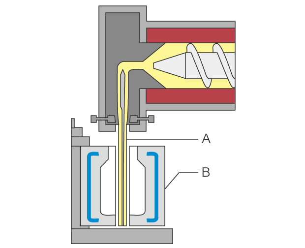
A : Parison (hot parison) B : Mold
[Flow of Molding]
-
1The molten plastic is extruded.
-
2A die is used to form a cylindrical shape called a parison (hot parison).
-
3The parison is placed inside the mold before it cools and solidifies.
-
4Air is blown into it to form the desired shape.
Injection Blow Molding (Injection Stretch or 2-Axis Stretch-Blow Molding)
The basic structure and principle of an injection blow molding machine are shown below. One typical product is plastic drink bottles made from polyethylene terephthalate (PET).
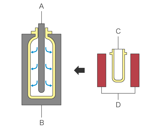
A : Stretch rod B : Mold C : Preform (cold parison) D : Heater
[Flow of Molding]
-
1Injection molding of thermoplastic resin is used to create a preform (cold parison) in a test tube shape in advance.
-
2The preform is heated and is set into the mold using a stretch rod.
-
3High-pressure air is blown into the preform to create the desired shape.
Multi-Layer Blow Molding
In order to prevent oxidizing and deterioration of the contents and to improve the strength, the material used for the parison is produced by co-extruding ethylene-vinyl alcohol copolymer (EVOH) or other material that has a high gas barrier property. This molding method is therefore suited for molding products such as plastic containers for cooking oil or seasonings, or gasoline tanks.
The basic principle of multi-layer blow molding is shown below.
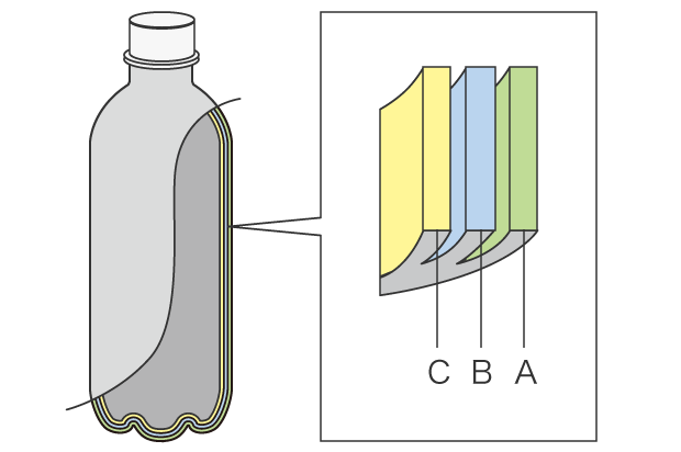
A : Polyethylene (PE) B : Bonding layer C : Ethylene vinyl alcohol (EVOH) copolymer
[Flow of Molding]
-
1Co-extrude two or more types of plastic material to form a multi-layer preform (cold parison).
-
2Heat the preform (cold parison).
-
3Air is blown into it to perform blow molding.
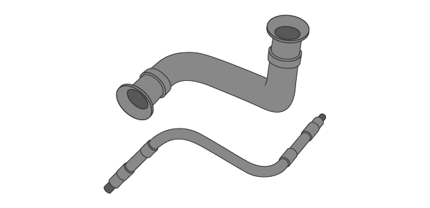
Three-Dimensional Blow Molding
form a three-dimensional shape that can help prevent material draw-down and burrs.
With this molding method, it is possible to create high-quality air-conditioner hoses, tubes, and other products that have complex shapes such as curves or bellows.
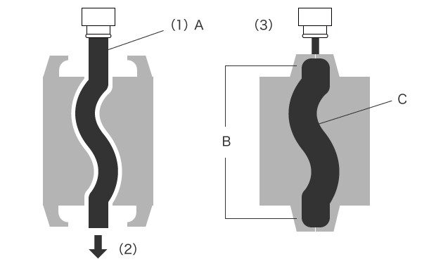
A : Plastic discharge B : Closing the top and bottom. C : Air injection
[Flow of Molding]
-
1The extruder accumulator is filled with plastic material, and a parison is formed.
-
2Air is suctioned from the exit on the opposite side. The parison enters the mold traveling along its inner shape until it reaches the mold bottom.
-
3Air is blown into it to perform blow molding.
Challenges in Measuring Plastic Molded Components
Getting accurate readings from molded plastic parts presents unique obstacles that other material types don't have. Many plastics flex under the slightest pressure from measurement probes. This means contact-based tools can actually change the shape you're trying to measure.
Temperature also plays a role. Parts fresh from the mold continue shifting as they cool completely. Even room temperature variations can cause slight dimensional changes. Add in the fact that most plastic mold parts have curves, undercuts, or thin walls, and you start to see why standard measurement approaches fall short.
Causes of Assembly/Fitting Defects in Plastic Molded Parts
With plastic molding, forming products is easier than with metals. It is also possible to use various materials to change the hardness or weight, and expression in a wide range of colors and shapes is possible. On the other hand, warpage, waviness, strain, short-shot, and other problems occur due to causes such as slight differences in material temperature or quantity, or minute distortion of the mold, and these may result in assembly failure or fitting failure.
Fitting failure means that the size of the plastic part is not correct and it cannot be assembled, or else a gap is produced when the plastic parts are joined or assembled. Forcibly assembling parts with fitting failures can damage the parts, or cause leakage of the contents in parts that require airtightness.
Warpage and Waviness
Warpage and waviness of plastic molded parts means that the workpiece is curved like a bow. These problems are also called “bending” or “twisting.”Warpage consists of forward warpage and reverse warpage, according to the direction of warping.
Waviness refers to surface irregularities produced by warpage in various directions. The primary causes of warpage and waviness in plastic molded parts are the following.
- Differences in plastic shrinking
- Uneven mold temperature
- Differences in the shrinkage rates of the molten plastics resulting from the direction of flow

Warpage

Waviness
Differences in Plastic Shrinking
Warpage occurs when differences in plastic shrinking occur due to variation of temperature or pressure inside the cavity. The amount of plastic shrinkage inside the cavity is proportional to temperature and inversely proportional to pressure. As a result, when a workpiece has both a thin part and a thick part, because the thin part has a lower temperature, the amount of shrinkage is smaller, and more shrinkage occurs at the thick part because it stores more heat. The difference in temperature results in a difference in plastic shrinking inside the cavity, causing the mode of deformation known as warpage.
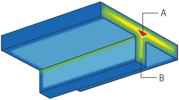
A : Larger shrinkage (thick part) B : Smaller shrinkage (thin part)
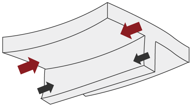
Red Arrow : Larger shrinkage Smaller shrinkage Black Arrow : Smaller shrinkage
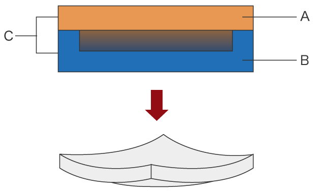
A : Larger shrinkage (higher temperature) B : Smaller shrinkage (lower temperature) C : Mold
Uneven Mold Temperature
Warpage occurs when differences in plastic shrinking occur inside the cavity due to uneven mold temperature. When the cooling time is different at different parts of the mold, this causes differences in plastic shrinking that result in warpage.
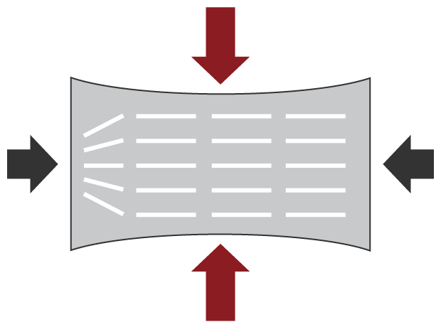
A : Glass fiber B : Gate position Red Arrow : Larger shrinkage Black Arrow : Smaller shrinkage
Differences in the Shrinkage Rates of the Molten Plastic Resulting from the Direction of Flow
Warpage or waviness occurs because the shrinkage rate is different depending on the direction of plastic flow. When the plastic contains a material such as glass fiber, the fiber becomes oriented in the direction where there is more plastic flow. As a result, shrinkage in the direction of plastic flow becomes smaller, and shrinkage in the direction perpendicular to the plastic flow increases. This is referred to as anisotropy of shrinkage due to fiber orientation, and it is a cause of warpage.
Strain
Strain in a plastic molded product is a phenomenon in which the entire workpiece becomes twisted or warped. It is caused primarily by residual stress. Residual stress in plastic molding means internal strain which remains in a plastic molded product. It includes tensile residual stress in which there is a force which acts toward the outside, and compressive residual stress which acts toward the inside.
Tensile residual stress is stress which pulls the inside of the molded product toward the outside. It occurs when molten plastic that was injected into the mold at high pressure begins cooling and solidifying inside the cavity starting from the outside. Compressive residual stress is stress occurring when the pressure applied to the mold in order to form the product acts to compress the plastic toward the inside.
Example of Strain Due to Compressive Residual Stress
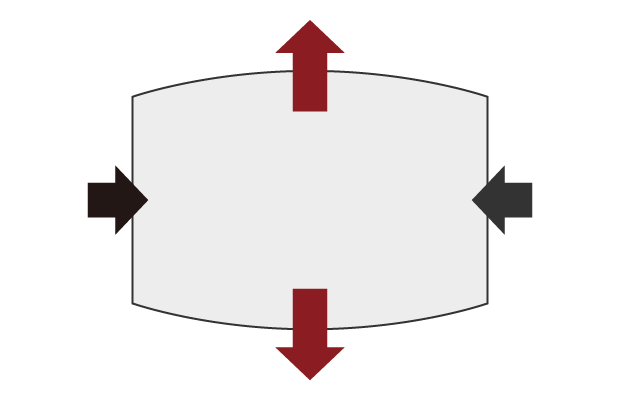
Red Arrow : Expansion Black Arrow : Compression
Example of Strain Due to Tensile Residual Stress
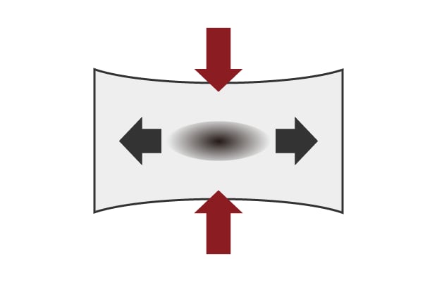
Red Arrow : Shrinking Black Arrow : Pulling
A plastic product where there is residual stress may not only lose its dimensional accuracy due to shrinkage or expansion, but may also cause deformation or cracking when the residual stress of the plastic product reacts to factors such as cutting, grinding, welding or other heating, and treatment or finishing using a coating or solvent. In addition, during manufacturing and processing, special caution is required because the shape may change due to strain that is produced as the product ages.
For this reason, the process called annealing may be used to eliminate residual stress.
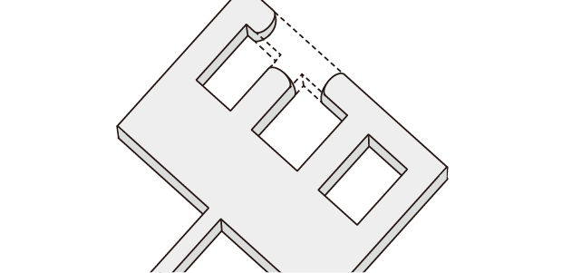
Short Shot
Short shot is a phenomenon in which part of the molded product shape is incomplete because the plastic material did not reach every corner of the mold cavity.
Major causes include solidification at the leading edge of the flow that causes the plastic to cool and solidify before reaching the most remote parts, resulting in an incomplete shape at certain parts. Another cause is trapping of air that prevents the plastic material from flowing smoothly into the mold.
Possible countermeasures to solidification at the leading edge of the flow include the following.
- Raise the temperature of the injected plastic.
- Increase the runner thickness.
- Increase the holding pressure or pressure hold time.
Possible countermeasures to air trapping include the following.
- Change the injection speed.
- Raise the cavity surface temperature.
- Change the flow pattern.
Common Issues with Traditional Measurement Methods
Standard measurement tools struggle with the demands of modern manufacturing. Contact-based instruments require you to choose specific points on a surface. If a critical area is missed, defects can slip through. The process also takes considerable time when parts have complex geometries.
Operator subjectivity can also cause variability in measurement. Two technicians measuring the same component with calipers often record different values. Probe pressure varies. Point selection differs. These inconsistencies make it hard to establish reliable quality baselines or track trends across production runs.
Measurement Difficulties
It is extremely important to confirm that the dimensions and shape of a plastic molded product are as intended (within the tolerances). In particular, because the fitting portion of a complex shaped part may affect assembly work or airtightness, highly accurate and quantitative 3D shape measurement is required.
Ordinarily, coordinate measuring machines or calipers are used for measurement; however, these methods involve a number of problems. These include the difficulty in achieving accurate measurement with a coordinate measuring machine and variation in measurement depending on the operator when using calipers.
Measurement Difficulties - CMM
When measuring warpage and waviness using a coordinate measuring machine, it is ordinarily necessary for the end of the probe to contact four or more points at the corners of the target measurement surface.
In the case of a plate, for example, generally six to eight points are measured. When the measurement area is large, measurement accuracy can be improved by increasing the number of measured points to collect more measurement data.
However, measurement of warpage and waviness involves the following problems.
- Because it is necessary to measure by contacting individual points, it is difficult to identify the shape of the entire target.
- Measuring more points to acquire more measurement data requires a lot of time, and it is not possible to identify the detailed shape of the entire target.
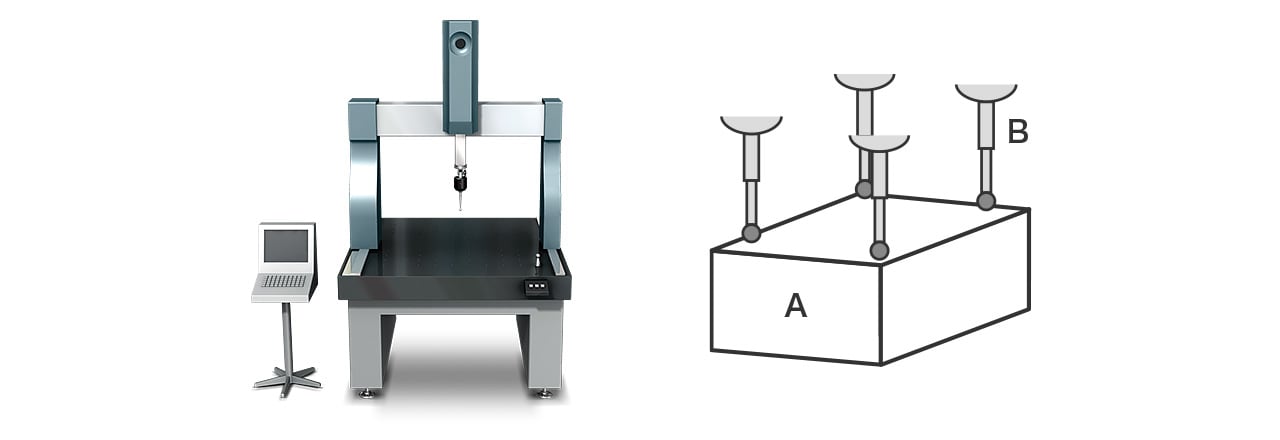
A : Target B : Probe
Measurement Difficulties - Calipers
Hand-held tools such as calipers are very convenient for measurement. However, there are multiple causes which result in measurement error or variation in the measurement data.
With calipers, measurement conditions such as the contact force (measuring force) when measuring each point by hand and selection of the measured points differ depending on the operator. This results in variation in the measurement values and makes it difficult to obtain quantitative measurements. For warpage and waviness over a wide area, many points must be measured, and inspections require a long time.
How 3D Scanners Improve Plastic Part Measurement
When you measure plastic molded parts with a 3D scanner, you capture millions of data points in minutes . The technology works by projecting light patterns onto the surface and recording how those patterns deform. Software then builds a complete digital model without ever touching the component.
This approach eliminates the guesswork. By comparing scanned data directly against the CAD model, you see exactly where variations occur across the entire surface. For plastic injection molding operations, this means catching mold wear or process drift before bad parts reach assembly.
Plastic Molded Parts Measurement Solutions
Reviewing the problems of conventionally used measuring instruments shows that there is a certain point which the problems all have in common. This is the measurement of a three-dimensional target or area is done by means of point and line contact.
To resolve these measurement problems, KEYENCE has developed the 3D Scanner CMM VL Series. The VL Series accurately captures the 3D shape of the entire target surface without contacting the target. A 3D scan of the target on the stage can be completed in as little as one second, for high-accuracy measurement of the 3D shape. This allows instantaneous quantitative measurement that is free of variation in the measurement results. Some specific examples of the advantages are explained below.
Non-Contact 3D Scanning for Delicate Plastic Parts
Softer materials like plastic pose special problems for quality control. Press too hard with a caliper and you compress the surface. Probe a thin wall with a CMM, and you risk puncturing it. Non-contact scanning solves both issues by keeping measurement tools away from the part entirely.
Improving Accuracy and Repeatability
Production environments demand consistency. With traditional, contact-based methods like calipers,, results can vary depending on who is taking the measurement. 3D scanners deliver the same results regardless of who is using them.
The system captures data the same way every time. No judgment calls about where to place a probe. No variation in applied force. When you need to measure plastic molded parts across multiple shifts or facilities, this repeatability becomes critical for maintaining specifications.
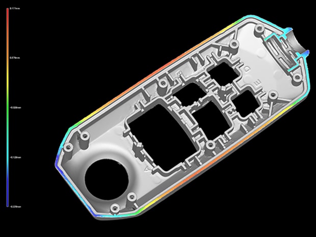
Advantage 1: Scanning the 3D Shape of a Surface Allows Warpage and Waviness to Be Identified at a Glance
When a plastic product with a complex shape is measured using a CMM or calipers, measurement requires much time because of the many points that must be measured. Because only individual points are measured, it is difficult to measure the 3D shape of the target.
With the VL Series, you only need to place the target on the stage and scan it. The 3D shape of the target can be captured by non-contact means, and no positioning is required. As profile measurement is also possible at any part of the target, it is possible to visualize and identify the locations and precise numerical values of shape defects.
This allows easy checking of the mold and molding conditions for trial products, and allows the causes of assembly failures to be smoothly identified and corrected in commercial products. Because the shape data is measured quantitatively, it is possible to easily control warpage and waviness based on tolerances, and to use the measurements for trend analysis.
Evaluation of Remote Controller Cover Shape
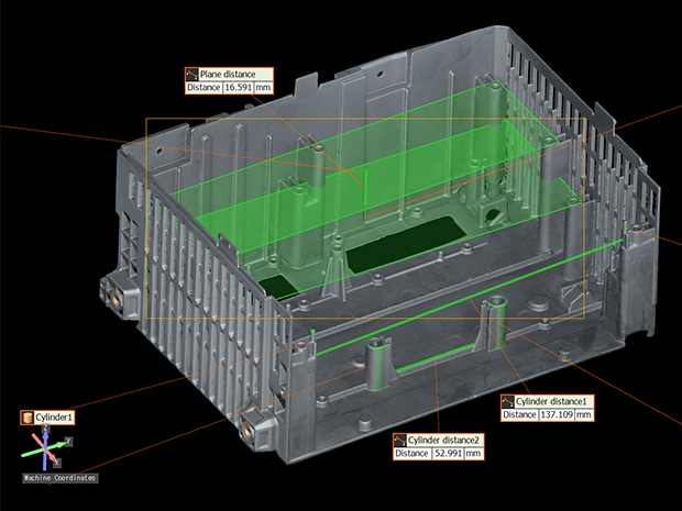
Wide Range of Tools for Precision Measurement
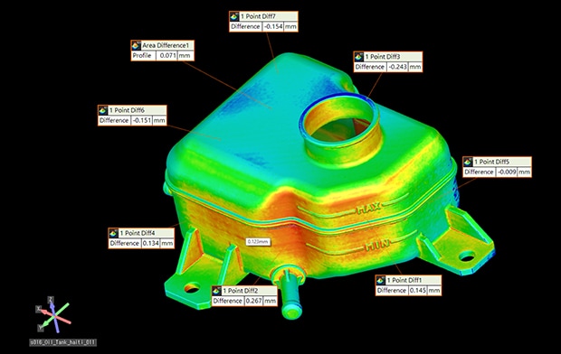
Advantage 2: Visualize Differences from the 3D-CAD Data in Color
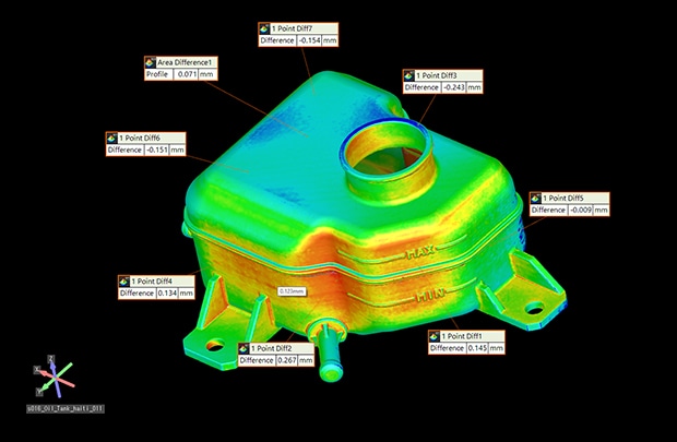
It is possible to compare a product’s 3D-CAD data with the acquired measurement data to visualize any differences between the actual product and the design. For objects that were difficult to measure by conventional means, comparing the measurement results with the 3D-CAD data allows previously undetected defects to be identified. This is effective for inspections and also for cause analysis of defective fitting parts.
Because a wide range of dimensional measurements is supported, precisely measuring the dimensions at locations of concern allows problems to be analyzed in detail.
Comparison with Oil Tank Cad
Dimensional Measurement at Specific Locations
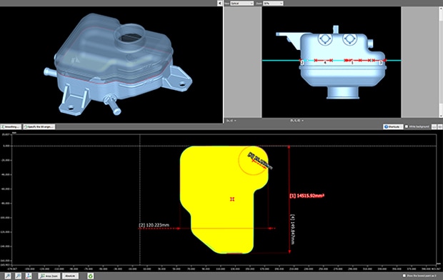
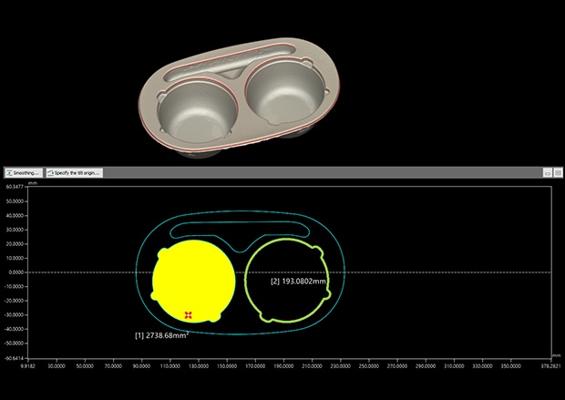
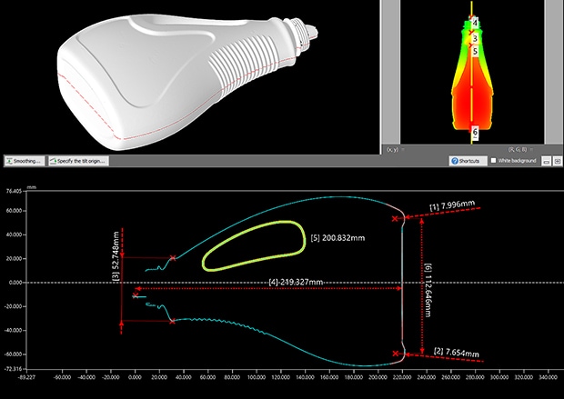
Advantage 3: Cross-Section Analysis Can Be Performed Without Cutting the Sample
Cross-sections that are difficult to measure by conventional means can be created by non-destructive means that allow detailed measurement and analysis. Reference planes can be set as needed in the 3D shape data and cross-section measurement can be performed from every direction.
Food Container (Cross-Section Area Measurement)
Plastic Bottle (Performance Evaluation of Functional Locations)
Applications in Inspection and Reverse Engineering
3D scanning does much more for plastic part manufacturing than simple dimensional checks. It speeds up product development and improves quality control by giving fast and accurate insight. For example:
Quality inspectors use 3D scanning throughout the production cycle to perform the following:
- First article inspection: Confirms whether new molds produce parts within tolerance.
- In-process checks: Catch issues like warpage, flash, or shrinkage before they become widespread.
- Final inspection: Verifies that everything leaving your facility meets customer specifications.
Reverse Engineering Applications Are Helpful For:
- Recreating a legacy component or competitive part by capturing every curve and feature.
- Importing captured scan data directly into CAD software.
- Modifying an existing part.
- Cutting weeks off traditional reverse engineering timelines while improving accuracy.
Summary: Higher Efficiency Measurement of Plastic Molded Parts
With the VL Series, high-speed 3D scanning allows instantaneous, non-contact, and accurate measurement of 3D shapes for plastic molded products, offering the following advantages:
- Because the entire surface is measured, it is possible to identify all defect locations on the target, and to perform profile measurement at any desired part.
- Non-contact, high-accuracy shape measurement is possible even for soft targets such as rubber and flexible plastic.
- No positioning is required. Just place the target on the stage and press a button to complete measurement.
- The 3D shapes can be displayed in a color map. By sharing data that is easy to understand visually, countermeasures can be smoothly enacted for problems such as warpage, waviness, strain, and short shot.
- Multiple sets of measurement data can be easily and quantitatively compared and analyzed.
- OK/NG product judgments are possible. Data can be shared for rapid analysis of NG products.
In this way, the VL Series can deliver dramatic improvements in thickness measurement efficiency and defect analysis.

Frequently Asked Questions
How Do You Measure Plastic Molded Parts Accurately?
Use non-contact 3D scanning to capture complete surface geometry without deforming soft materials. This eliminates operator variation and provides millions of data points for thorough analysis.
Why Use a 3D Scanner for Plastic Part Inspection?
3D scanners capture entire surfaces in seconds rather than sampling individual points, revealing defects that traditional methods miss while maintaining consistent results across different operators.
Can 3D Scanners Measure Flexible or Soft Materials?
Yes, because the measurement happens without physical contact, flexible components remain in their natural state and won't compress or deform during inspection.
How Is 3D Scanning Used in Reverse Engineering Plastic Parts?
3D scanning creates detailed digital models of existing components that import directly into CAD software, allowing you to recreate or modify designs without manual measurement. Similar techniques apply to casting applications where complex geometries need documentation.