3D Scanner
How to Optimize Sheet Metal Inspection
Key Takeaways
- Sheet metal inspection requires capturing full 3D geometry to quantify warpage and distortion.
- Contact-based tools like calipers and dial gauges miss the full picture and can vary based on the operator.
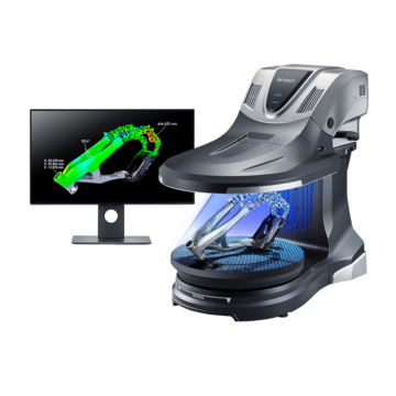
- The KEYENCE VL Series 3D Scanner CMM provides CAD comparison to visualize defects quickly.
- Full 3D scans let you check dimensions, measure thickness, and inspect small radii anywhere on your part.
- Full 360° scanning speeds up inspection and reduces manual effort for large or complex parts.
Sheet metal refers to thin, flat metal stock such as steel, aluminum, or stainless steel that can be formed into parts and assemblies. Transforming these raw plates into functional parts is called sheet metal fabrication, a set of manufacturing techniques that includes cutting, punching, bending, forming, and welding. These operations are used across industries for everything from appliance housings and automotive body panels to architectural cladding and aircraft components.
Because sheet metal parts frequently incorporate bends, flanges, holes, and compound curves, fabrication steps can introduce distortion, springback, and localized warpage. Those defects make it challenging to verify that a finished part matches its intended shape and dimensions. Single-point checks and manual inspections often miss subtle surface deviations and are slow or inconsistent with complex geometries. This page covers the basics of sheet metal fabrication and shows how to improve inspection of sheet metal parts.
About Sheet Metal Fabrication
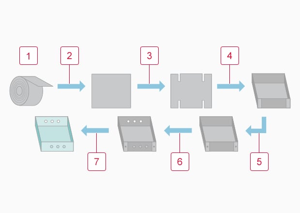
Sheet metal fabrication involves cutting, bending, welding, and surface finishing a metal plate to form the intended shape. The order varies by part, but typically the plate is first cut to dimensions on a shearing machine, then punched on an NC (numerical control) turret punch press, bent on a press brake, and joined by spot welding. Final surface finishing steps commonly include drilling, polishing, cleaning, and painting.
-
1Sheet material
-
2Shearing (shearing process)
-
3Turret punch processing (turret punching)
-
4Press brake
-
5Spot welding
-
6Drilling & polishing
-
7Cleaning & painting
Main Processes of Sheet Metal Fabrication
Cutting/Punching
Cutting and punching are the first steps in shaping a metal plate to the dimensions shown on a drawing. Cutting separates material along a line and is commonly done by shearing (mechanical blade cutting) or by laser cutting, which melts or vaporizes material with a focused beam. Punching removes shapes such as holes or slots by driving a punch through the sheet, typically using a turret punch press that can perform many different hole patterns quickly. When a plate is cut or punched to the required outline it is called blanking, and the piece produced is referred to as a blank.
Bending
Bending turns a flat, cut metal plate into the angled or formed features required by the drawing. Shops perform bending on a press brake, which uses a punch and die to apply force along a straight line and create a controlled fold. Different bending techniques include air bending, where the workpiece does not fully contact the die, and bottoming or coining, where the punch forces the material fully into the die for a more exact angle. Tooling geometry and bend radius determine how the metal flows and how much the material springs back after the load is removed. Because bending relies on matched punch-and-die tooling, it resembles stamping in its dependence on tooling accuracy and repeatability.
Welding
Welding joins sheet metal parts into assemblies and finished products. It is used to create strong, permanent connections where seams, brackets, stiffeners, or structural joints are required. In sheet metal fabrication, welding serves three main purposes: assembling components, restoring or reinforcing cut or formed edges, and attaching features such as tabs, bosses, or mounts. The following are common welding methods used in sheet metal fabrication.
YAG Laser Welding
YAG (Yttrium Aluminum Garnet) laser welding produces a small heat-affected zone and minimal distortion in thin steel plates, making it ideal for precision sheet metal fabrication.
Semi-automatic Welding
Semi-automatic welding needs an operator but uses an automatic wire feed, which lets you weld faster. It is classified as CO2, MAG, or MIG depending on the shielding gas used.
TIG Welding
TIG (Tungsten Inert Gas) welding uses argon as a shielding gas and can join various materials, including stainless steel and aluminum. It is known for its quality post-weld finish and is often used for products where appearance is important.
Spot Welding
Spot welding joins parts by clamping them between electrodes and applying an electric current at a single location. The current generates heat in the overlapped plates to form the weld. It is suitable for joining thin plates but is generally ineffective on thick plates.
Stud Welding
Stud welding joins studs, such as bolts or nuts, to a metal plate. The weld is quick, has little effect on the base material, and takes minimal time to complete.
Difference Between Sheet Metal Fabrication and Stamping
Both sheet metal and press processing rely on deformation of the metal, so sheet metal work can be considered a subset of press processing. In practice, however, sheet metal shops most often use general-purpose tooling to perform bending and simple forming, while press processing uses dedicated dies to produce more complex, multi-step shapes.
Press processing comes in several types:
- Single-hit (single-stroke) press: The operator places each workpiece into the press, the machine performs one operation, and the operator removes the part by hand. This method is suitable for low-volume production of large parts. It is simple and flexible but cannot be easily automated for continuous high-speed production because each stroke performs only one operation.
- Progressive press: A progressive press uses a long die with multiple stations. Coil material is fed forward a short distance each stroke so that each station performs a different operation in sequence. Because the strip moves continuously through the die without part transfer between stations, progressive presses produce complex parts quickly and are well suited for high-volume, automated production.
- Transfer press: A transfer press combines single-operation press stations with a mechanical transfer system that moves the workpiece from one station to the next. This approach handles larger or heavier parts than progressive tooling can, and it can achieve high yields. Transfer presses are commonly used when part size, complexity, or the need for stronger forming forces makes progressive tooling impractical.
What is Precision Sheet Metal Fabrication?
Regular sheet metal work typically uses plate thicknesses of about 1 to 4 mm. Precision sheet metal fabrication, by contrast, works with much thinner stock (roughly 0.1 to 3 mm) when tighter dimensional control is required. This finer-gauge material is common for parts in electronic devices, communications equipment, and semiconductor manufacturing machines, where complex geometries, many bends, and closely controlled hole locations are typical. These applications demand repeatable forming and tight tolerance control to ensure proper fit, function, and assembly.
Challenges in Conventional Sheet Metal Inspection
Sheet metal fabrication uses multiple steps, so parts frequently have complex geometries. Deformation like distortion and warpage can occur during each stage, making dimensional inspection necessary. Inspection is particularly challenging for precision sheet metal fabrication, which require higher tolerances.
Challenges of Measurement with Calipers
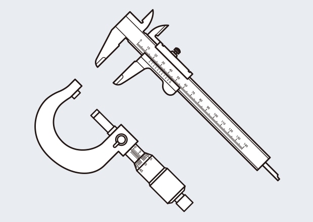
Calipers are widely used for dimensional measurement. However, for complex sheet metal parts, they struggle to represent the overall geometry and to find entire defects. Also, people can measure differently, leading to variation in results.
Evaluation of Welding Distortion
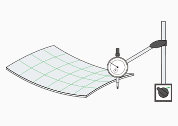
Welding joins parts in sheet metal fabrication, but the heat it produces causes distortion, warpage, and waviness. Thin steel plates are especially prone to these effects. Conventional tools like calipers or dial gauges make it hard to quantify overall distortion. Calipers can check a single point, but measuring the whole surface takes a lot of time and many measurement points.
Solving Issues with Sheet Metal Inspection
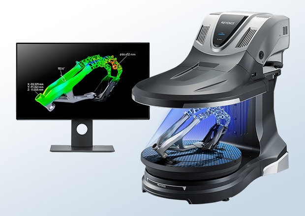
To address inspection challenges for sheet metal parts, you need an accurate view of the overall shape and dimensions. KEYENCE’s 3D Scanner CMM, the VL Series, solves this problem. The VL Series captures a full 360° scan of an object, enabling high-precision 3D measurements. You can compare scans to 3D CAD data and quickly see differences with a color map. The system also supports part-to-part comparison & thickness checks at any point on the part, making previously hidden defects immediately obvious.
Benefit 1: Quantify deviation across your entire part
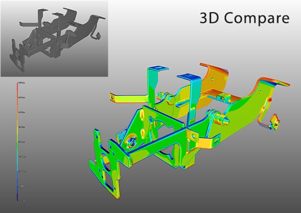
Calipers and dial gauges only give you spot checks, so it was hard to see how much welding warped the whole part. With KEYENCE’s VL Series 3D Scanner CMM you can scan the whole piece and compare the result with 3D-CAD to measure distortion precisely.
Benefit 2: Easily perform dimensional measurements at any point
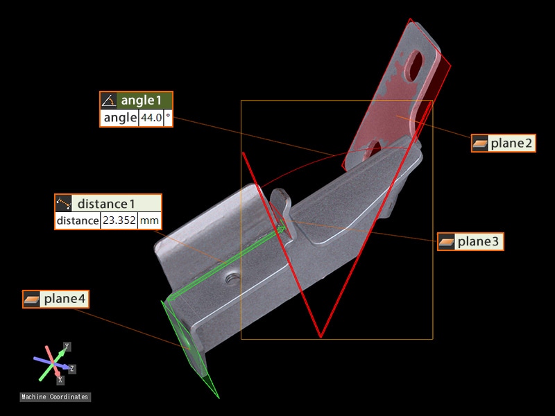
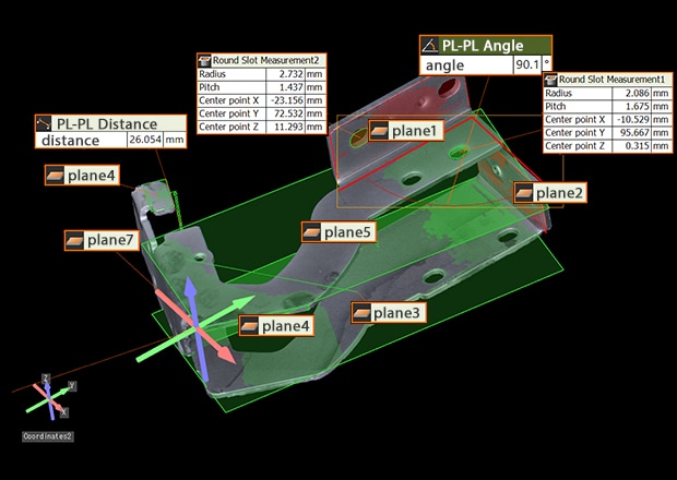
Dimensional measurement of complex sheet metal require substantial effort. The KEYENCE VL Series 3D Scanner CMM acquires complete part data so measurements can be made at any point. It supports coordinate measurements from XYZ data and performs geometric tolerance inspections.
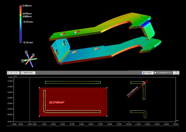
Benefit 3: Accurately measure small radii, such as in bent sections.
Small radii and similar features are hard to measure with conventional methods. With KEYENCE’s VL Series 3D Scanner CMM, even tiny radii in bent areas can be measured accurately. You can also compare scans to a CAD model or reference part. For example, you can easily evaluate deformation of hinge sheet metal parts after durability testing (pictured).
Optimize Sheet Metal Inspection: Achieve Significant Efficiency Gains with Accurate and Easy Comparisons
Parts that were difficult and time-consuming to inspect with conventional methods can be measured quickly using the KEYENCE VL Series 3D Scanner CMM. The system simplifies comparison with 3D CAD, improves measurement accuracy, and reduces man-hours needed for inspection.
- A full 360° scan can be done in minutes, greatly cutting measurement time.
- Scanned data can be compared directly to CAD to identify deviations around entire parts.
- Large parts can be captured in a single shot, so inspection is not limited by part size.
- For complex shapes that traditional methods struggle with, 3D scanners can measure with ease.
- It accurately measures small radius bends, making it suitable for precision sheet metal inspection.
- Because the whole part is scanned at once, thickness can be measured at any point.